-
This Blood-Sampling Cytometer Is Small Enough for Mars

The race for Mars is on. NASA hopes to land the first Martian in the next decade, and the agency’s not alone: The China National Space Administration, Indian Space Research Organization, and Russia’s Roscosmos, as well as Elon Musk’s SpaceX have similar aspirations.
Yet the trip to Mars a long journey, filled with questions about how interplanetary trips affect human health. A paper published in Nature Communications puts the spotlight on a device that is helping to find answers: the rHealth One, a single-drop flow cytometer. The rHealth One was sent to the International Space Station (ISS) in 2022 to test its capabilities in orbit, and the results from that experiment have implications for health on Earth as well as Mars.
“The rHealth One exceeded expectations,” says Eugene Chan, CEO of rHealth. “[We’re] putting it on a rocket that goes up to nine Gs during launch, and when it gets up there, it’s in zero gravity... the fact that everything worked out perfectly kind of blows my mind.”
Re-thinking the Cytometer for Life in Space
Flow cytometers are an important diagnostic instrument that blasts cells with laser light and identifies different types of cells based on how light scatters. They were popularized in the 1970s as an alternative to viewing cells through a microscope.
“If you’re looking at cells in your blood in a microscope, you see red blood cells... but if you are after the more interesting type of cells, the white blood cells and their subtypes, you’re almost missing them because you’re overwhelmed by all the other cells. The flow cytometer really revolutionized that problem,” says Edwin van der Pol, assistant professor of biomedical engineering and physics at Amsterdam University Medical Center.
But conventional flow cytometers have a downside: They’re large and heavy. Most are desktop devices that weigh between 20 and 120 kilograms. That’s not a major issue in a medical facility but when it comes to launching a device into space, every kilogram counts.
“The fact that everything worked out perfectly kind of blows my mind.” —Eugene Chan, rHealth
“What we’ve been able to do is shrink this thing down a hundredfold in terms of mass, volume, and power, so that the entire cytometer is the size of a matchbox, and that fits inside the [rHealth One],” says Chan. The rHealth One weighs 1.5 kilograms and measures roughly 18 centimeters long, and 13 centimeters deep and tall.
To shrink the cytometer, rHealth One rethought the engineering of a flow cytometer with a focus on miniaturization. The printed circuit boards are cut down and integrated, the optical module is simplified, and the laser is reduced in size and output.
“If you compare the rHealth One to any flow cytometer that you can now commercially buy, it’s a big revolution,” says van der Pol. That’s not to say the rHealth One is a replacement for its predecessors: Rather, focusing on miniaturization and durability makes it possible to re-think assumptions of how a cytometer should be engineered.
The optical system is a key example. Most cytometers have optical systems that provide adjustments for future correction and calibration, while the rHealth One uses epoxy to fasten and seal the “optical block,” which reduces complexity, increases durability, and prevents unwanted movement when used in a zero-gravity environment.
Bringing the Cytometer Home
Once aboard the International Space Station, the rHealth One was tasked with measuring three types of prepared samples that contained a variety of particles designed to test the cytometer’s accuracy. Each sample was observed on Earth, then again on the ISS. The rHealth One’s results were largely on-target, with one exception: a single sample returned unexpected readings.
“The NASA guys said, hey, that doesn’t look like what the sample is supposed to be,” said Chan. “Maybe the astronaut carrying it it put in some corner of the spacecraft that is a little colder, or warmer, or whatever.” The sample was sent to Johnson Space Center for further analysis, which found the rHealth One’s unexpected measurements were accurate. Something—what, exactly, is unknown—had altered the sample in transit.
That underscores why a cytometer can prove useful in space. A long journey through space is likely to have unexpected impacts on the astronauts making the trip, as well as other living organisms sent on the journey. A cytometer gives astronauts en-route (or on) Mars a tool to analyze cells and observe changes that might otherwise go unnoticed.
And it holds potential on our home planet, as well. “In a home-based setting you can take more measurements, you can capture more points in time, to make sure you’re catching events and don’t miss anything,” said Eugene.
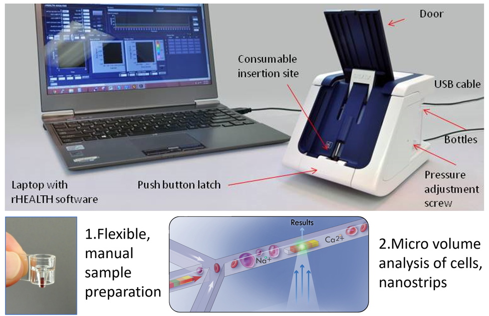 The rHealth One can connect to an ordinary laptop by a USB cable.rHealth
The rHealth One’s design already hints at this direction. Aboard the ISS, the device’s power and data were provided over a USB cable to a laptop running rHealth’s software. Sample runs averaged more than 71 million raw data points and were streamed in real-time, with reach run completing in roughly two minutes.
Chan said people undergoing cancer treatment are one group who could benefit. Cancer treatment typically includes frequent blood counts which currently must happen in a medical setting. Bringing a cytometer into the home would allow more frequent and convenient testing. That could also prove useful for people with other conditions that require frequent testing, such as blood cell disorders.
A future version of the device, the rHealth Awesome, will look to further refine the design and software for ease of use. “Essentially, you can get all the diagnostics that you would using the rHealth One through a fairly dumbed-down app. That’s where we are right now, and I think we’re close to achieving victory on that as well,” said Chan.
-
Tiny Sensor Aims to Monitor Tumors in Real Time

This article is part of our exclusive IEEE Journal Watch series in partnership with IEEE Xplore.
A tiny sensor could one day be placed next to tumors to monitor patients’ responses to cancer in real time. Researchers at the University of California, Berkeley and the University of California, San Francisco, described a prototype sensor in a study published 12 March in IEEE Transactions on Biomedical Circuits and Systems. The researchers used the prototype to demonstrate in a proof-of-concept that the sensor can monitor biological changes in the tissues of mice.
During the early stages of cancer treatment, it can be difficult to assess whether a therapy is working. As of now, the best way to understand how well a patient is responding to therapy is through a biopsy, where small tissue samples of the tumor are taken from patients and analyzed under a microscope in a laboratory. However, biopsies require a lot of time and resources, and ultimately can only provide doctors with a snapshot in time of how well the cancer treatment is working.
“Currently, there is no way to mechanistically monitor response [to treatment] in real-time in tissue deep within the patient,” says Rozhan Rabbani, a graduate student at the University of California, Berkeley. Rabbani adds that implantable biomedical sensors could overcome this issue and provide patients with more personalized treatment plans.
Rabbani and her colleagues set out to create a novel wireless image sensor in hopes of providing real-time monitoring. The sensor transmits data using ultrasound, which can safely penetrate skin and other bodily tissues. The sensor is also powered by ultrasound, by harvesting the vibrational energy from the ultrasound waves and storing it in an off-chip capacitor.
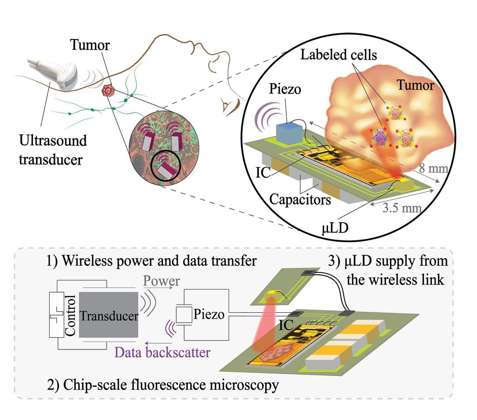 A diagram showing the different components of the novel image sensor, which is powered by ultrasound and could one day offer real-time monitoring of tumors.Rozhan Rabanni et al.
A small laser on the image sensor provides localized illumination, while the sensor itself converts the light into digital signals. Another miniature device, called a collimator, enhances image resolution. “This technology restricts the angle of incident light, resulting in sharper images with higher resolution,” explains Rabbani.
The image sensor, with an integrated circuit just 2.4 by 4.7 millimeters in size, then transmits the data it gathers back outside of a patient’s body, again using ultrasound.
After designing the sensor, Rabbani and her colleagues conducted experiments using mice. For these initial experiments, the researchers did not study tumors in live mice. Instead, they tested the ability of their sensor to simply analyze tissue samples taken from the mice before and after anti-cancer therapy, comparing these images to ones taken by a traditional microscope.
The mice were given anti-cancer therapy, and the tissue samples from the mice were imaged at the beginning of the experiment (untreated group) and after 18 days (treated group). The results show that the novel sensor was able to detect changes in the tissue samples between the two groups as the mice responded to their cancer treatment and more immune cells were found in their tissue samples. For example, the microscope was able to detect a 10 percent increase in the presence of immune cells after treatment, while the image sensor was able to detect a 17 percent increase.
While these results demonstrate that the sensor can capture changes in bodily tissues over time to a similar extent as a fluorescence microscope, more research is needed to ensure the device can safely be implanted in mice and humans without being rejected by the recipient’s immune system.
“Factors such as size, shape, flexibility, and material type play significant roles in determining in vivo biocompatibility,” says Mekhail Anwar, an associate professor at both UC San Francisco’s Department of Radiation Oncology and UC Berkeley’s Department of Electrical Engineering. “Strategies to reduce device size and enhance biocompatibility, such as using organic materials for encapsulation, need to be explored.”
Although the sensor prototype is capable of monitoring clusters of cells over time, its resolution is still not the same as a microscope. Therefore the research team has plans to build upon their sensor’s capabilities. “We are actively working on new technologies to enhance resolution and broaden the application beyond identifying changes in multicell populations,” says Anwar.
“We are hoping that in the future, when we have a fully implantable system, we can monitor the same mouse over time,” Rabbani says.
-
Blink to Generate Power for Smart Contact Lenses

The potential use cases for smart contacts are compelling and varied. Pop a lens on your eye and monitor health metrics like glucose levels; receive targeted drug delivery for ocular diseases; experience augmented reality and read news updates with displays of information literally in your face.
But the eye is quite a challenge for electronics design: With one of the highest nerve densities of any human tissue, the cornea is 300 to 600 times as sensitive as our skin. Researchers have developed small, flexible chips, but power sources have proved more difficult, as big batteries and wires clearly won’t do here. Existing applications offer less-than-ideal solutions like overnight induction charging and other designs that rely on some type of external battery.
Now, a team from the University of Utah says they’ve developed a better solution: an all-in-one hybrid energy-generation unit specifically designed for eye-based tech.
In a paper published in the journal Small on 13 March, the researchers describe how they built the device, combining a flexible silicon solar cell with a new device that converts tears to energy. The system can reliably supply enough electricity to operate smart contacts and other ocular devices.
This is a major improvement over wireless power transfer from separate batteries, says Erfan Pourshaban, who worked on the system while a doctoral student at University of Utah.
“Most current research includes a wireless power transfer with one antenna on the lens and another in a device that can be only about a centimeter away—a very, very tiny gap,” says Pourshaban, who is now a process-integration engineer at Texas Instruments. “It has to be right in your line of vision, which isn’t practical. We felt, if you can’t really wear it around, then it doesn’t matter if a smart contact’s actual technology is great. We’ve got to build a unit that can stand on its own.”
Photovoltaics and Metal-Air Batteries
To create the power pack, Pourshaban and his colleagues fabricated custom pieces. The first step was miniaturized, flexible silicon solar cells that can capture light from the sun as well as from artificial sources like lamps. The team connected eight tiny (1.5 by 1.5 by 0.1 millimeters) rigid crystalline cells and encapsulated them in a polymer to make a flexible photovoltaic system.
The second half is an eye-blinking-activated system that functions like a metal-air battery. The wearer’s natural tears—more specifically the electrolytes within them—serve as a biofuel to generate power.
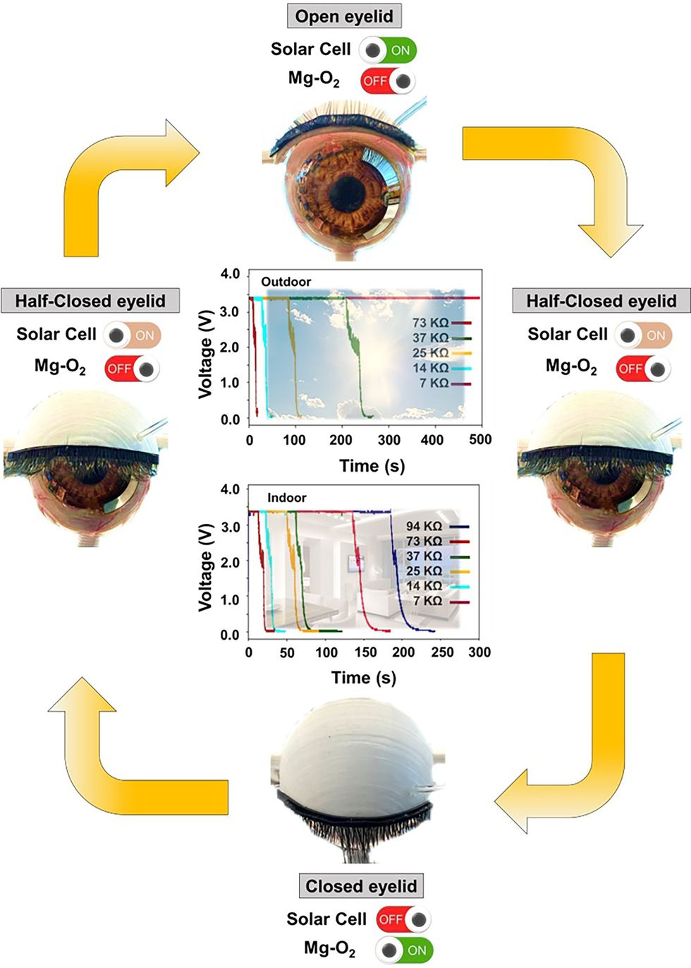 The photovoltaics and the battery activate at different phases of blinking.Erfan Pourshaban
The harvesting occurs literally in the blink of an eye: When the eye is completely open, the harvester is off. Then when the eye starts to blink, the tear electrolytes meet the magnesium anode, causing an oxidation reaction and the generation of electrons. Finally the tear electrolytes come into contact with both an anode and the platinum cathode, creating more energy through further oxidation on the surface of the anode and oxygen reduction on the surface of the cathode. The electrodes are kept from fouling by the motion of the eyelid and continual refreshing of the tears.
The two “halves” of this energy generation come together via a power-management circuit with an integrated 11-millifarad supercapacitor—which converts the voltages to DC, boosts them, and ultimately delivers about 150 microwatts of power at a stable 3.3 volts—no antennae, external battery pack, or special charging case required.
This system is “an exciting development in the realm of smart contact lenses,” says Wei Gao, a biosensors expert and assistant professor of medical engineering at Caltech, who was not involved in the research. He notes the promise of smart contacts has been hampered given that the “key hurdle for these devices is their need for a sustainable power source.”
This new power pack is not only “user friendly,” he notes, but also an “innovative dual-mode approach” that leverages two modes of energy harvesting so that it’s continuously happening—whether the eyes are open or closed.
“The reliable power output from this device can fuel a broad spectrum of applications, including wearable biosensors and electrically responsive drug-delivery systems, directly within the eye’s environment,” Gao adds.
Glaucoma and Other Applications
Pourshaban agrees, adding that there are obvious consumer applications, such as lenses that display to a runner the heart rate, pace, and calorie burn during a workout. Retailers could glean valuable insights from tracking how a shopper scans shelves and selects items. Commercialization potential is significant and varied, he says.
However, Pourshaban is perhaps most excited about potential applications in monitoring eye health, from prosaic conditions like presbyopia—age-related farsightedness, which can begin in the mid-40s—to more insidious diseases including glaucoma.
“Glaucoma is known as the silent thief of sight: There’s no pain, there may be nothing you notice, and then suddenly if the eye pressure gets to be too much in between your eye-doctor visits, you can irreversibly lose vision,” Pourshaban says. “If we could have real-time detection of warning signs for these and other conditions—and intervene quickly—it can change the course of a person’s life.”
-
Tiny Biosensor Is Just a Cup, a Membrane, and a Magnet

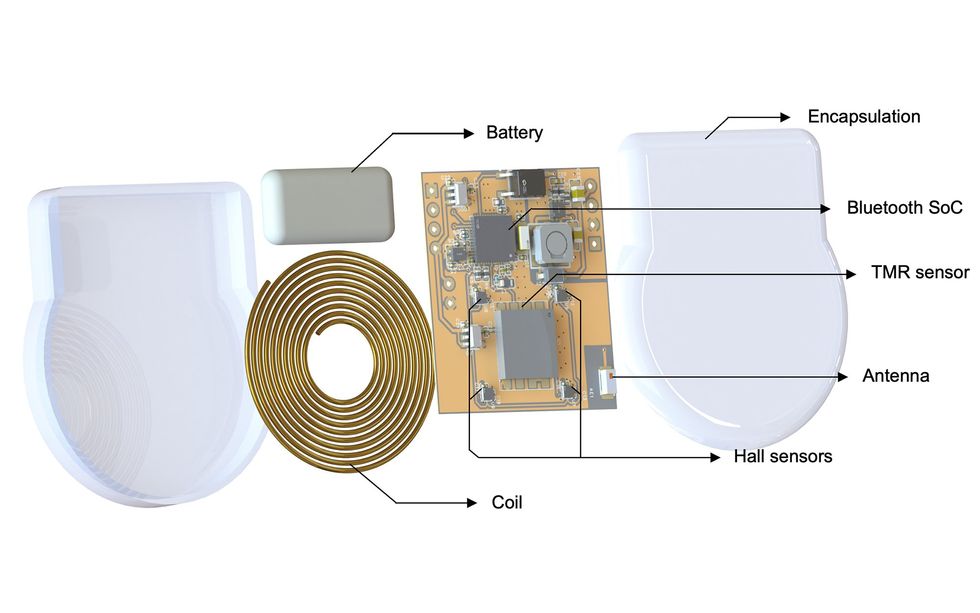
A wireless, chipless prototype biosensor offers the prospect of simple, wearable tech that can continuously monitor blood-sugar levels and other biochemical and physiological markers. The system pairs an implanted, magnetic biosensor with a miniature, wearable device that relays the sensor’s magnetic signals to a smartphone via Bluetooth.
The implant is smaller than most pencil erasers. It is in fact a plastic cup covered with a thin, flexible membrane, on which is glued a minuscule magnet. The wearable reader is a magnetic-signal transmitter-receiver about the size of a stack of three or four American Kennedy half-dollars or EU 10-euro collector coins.
The batteryless implant contains just three components made of three materials: a 6-millimeter-diameter silicone polymer cup, a 6-mm-diameter membrane of the same material, and a 1.5-by-0.8-mm cylindrical micromagnet.
With membrane and magnet in place over the cup, the finished device is like a tiny kettledrum: Thump on it, and the drumhead vibrates.
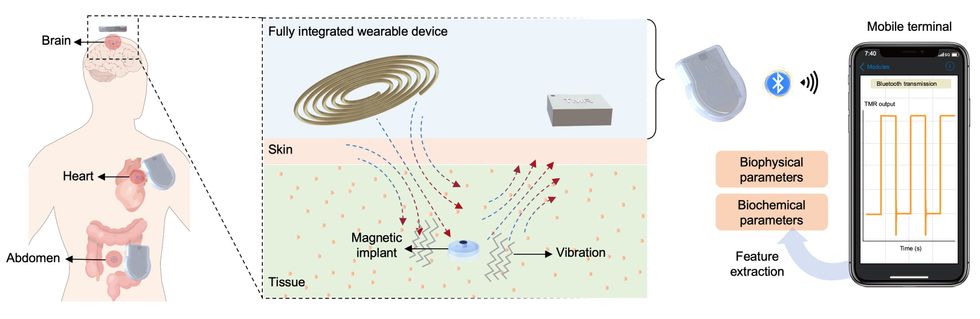 A magnetic implant vibrates signals out to a wearable device, whose coil picks up the signal and then routes it via Bluetooth to a smartphone for analysis.Mengdi Han Lab/University of Peking
“We refer to the implantable part as the magnetic implant and the wearable part as the miniaturized wearable device,” says Mengdi Han, assistant professor of biomedical engineering at Peking University’s College of Future Technology in China. “However, we have yet to devise a new, concise name for the system.”
The reader is a magnetic sensing device called a tunneling magnetoresistance (TMR) sensor, which picks up the motions of the implanted magnet and sends the signal via Bluetooth to a handheld device, where it is recorded and decoded.
 The wearable readout device, built around a tunnel magnetoresistance sensor (TMS), is the size of a small stack of U.S. half-dollar coins.Mengdi Han Lab/University of Peking
Or as Han describes it, “Our work uses an elastic membrane to generate large a variation of magnetic field, enabling us to use a mini wearable device to measure the signal continuously at any place.”
He adds, “We initially designed many complex 3D structures for the magnetic implant, but then realized that a simple cavity was more reliable.”
What the New Sensor Can Sense
In their proof-of-concept experiments, Han and his colleagues used unmodified implanted sensors to measure intracranial pressure and cerebrospinal fluid viscosity in rats.
To detect specific molecules in a living system, the researchers took a page from earlier work on magnetoelastic resonance sensors. “Our work indeed builds upon the foundation laid by previous research in magnetoelastic resonance sensors,” says Han.
The researchers expanded the surface area attached to the implanted magnet by gluing vertical arrays of multiwalled carbon nanotubes to its exposed surface. They then coated the nanotubes with proteins that grab onto the molecules they want to detect, increasing the inertia of the vibrating surface.
So, coating the sensor’s “drum” head with concanavalin A, a bean protein with a strong affinity for sugar molecules, produced a glucose sensor. Coating with specific antibodies produced real-time sensors for proteins like albumin and human immunoglobulin G.
“Compared with previous works, the major advantage of our work is that we use an elastic membrane as the vibration structure,” Han says. “The resulting vibration amplitudes reach millimeter-level, two orders of magnitude larger than conventional MEMS actuators. Such large amplitudes create obvious variations of magnetic field. Therefore, we can detect the change of magnetic field using sensors even with relatively low sensitivities, such as the TMR sensor chip integrated in our miniaturized wearable device.”
By contrast, the small vibrational amplitudes inherent in earlier devices demanded more sophisticated and expensive receivers, says Han.
“They need to rely on large coils to detect the high frequency change of magnetic field, or use lock-in electronics,” he adds. Some devices even demand expensive and bulky superconducting quantum interference device magnetometers (SQUIDs) or optically pumped magnetometers.
“I’m not sure if our device can surpass MEMS in terms of times and costs,” Han says. “However, I do think that our wearable reader can be at least 10 times cheaper than earlier bulky readout equipment.”
Han adds that the group is looking into commercial development of their prototype device. “There is a demand for wireless implantable sensors in various clinical scenarios,” he says. “Currently, we are focusing on enhancing long-term stability postimplantation.”
The researchers reported on their work earlier this month in the journal Science Advances.
-
Salt-Size Sensors Mimic the Brain

To gain a better understanding of the brain, why not draw inspiration from it? At least, that’s what researchers at Brown University did, by building a wireless communications system that mimics the brain using an array of tiny silicon sensors, each the size of a grain of sand. The researchers hope that the technology could one day be used in implantable brain-machine interfaces to read brain activity.
Each sensor, measuring 300 by 300 micrometers, acts as a wireless node in a large array, analogous to neurons in the brain. When a node senses an event, such as a change in temperature or neural activity, the device sends the data as a “spike” signal, consisting of a series of short radio-frequency pulses, to a central receiver. That receiver then decodes the information.
“The brain is exquisitely efficient in handling large amounts of data,” says Arto Nurmikko, a professor of engineering and physics at Brown University. That’s why his lab chose to develop a network of unobtrusive microsensors that are “neuromorphic,” meaning they are inspired by how the brain works. And the similarities don’t end there—Nurmikko says that the wireless signals and computing methods are also inspired by the brain. The team published their results on 19 March in Nature Electronics.
Thinking Like a Brain
Like neurons, these sensors are event-driven and send signals only to the receiver when a change occurs. While digital communication encodes information in a sequence of ones and zeros, this system cuts down the amount of data transmitted by using periods of inactivity to infer where zeros would be sent. Importantly, this leads to significant energy savings, which in turn allows for a larger collection of microsensors.
But with so many sensors sending information to a common receiver, it can be difficult to keep the data streams straight. The researchers deployed a neuromorphic computing technique to decode the signals in real time.
“The brain is exquisitely efficient in handling large amounts of data.” —Arto Nurmikko, Brown University
The researchers also conducted simulations to test the system’s error rate, which increases with more sensors. In addition to 78 fabricated sensors, they ran simulations of networks consisting of 200, 500, and 1,000 nodes using a real data set from primate brain recordings. In each, the system predicted the hand movement of a nonhuman primate with an error rate below 0.1 percent, which is acceptable for brain-computer applications. Nurmikko says the team will next test the wireless implanted sensor network in rodents.
While the technology could be applied to any part of the body where biomedical researchers aim to monitor physiological activity, the primary goal is use in a brain-machine interface that can probe a large region of the brain, says Nurmikko. The sensors could also be modified for use in wearable technology or environmental sensors.
There are key advantages of the system for biomedical uses, such as the small, unobtrusive design. But these applications also impose a key limitation: The sensors are externally powered by a wireless beam to avoid the need for batteries, and the body can only safely absorb so much radio-frequency energy. In other words, the system is not limited by bandwidth, but instead by power delivery. “From a practical point of view, it always comes back to the question of, where do you get your energy?” says Nurmikko.
Brain-Machine Interface Possibilities
The research provides “an important contribution, which demonstrates the feasibility and potential of neuromorphic communications for future use cases of low-power wireless sensing, communication, and decision making,” says Osvaldo Simeone, a professor at King’s College London and one of the researchers who first designed and simulated a neuromorphic communication system, in 2020.
The idea of a wireless network probing the brain is not new, says Federico Corradi, a researcher and assistant professor of electrical engineering at Eindhoven University of Technology, in the Netherlands. In 2011, for example, a researcher at the University of California, Berkeley, gave a presentation on “neural dust” in which he proposed a hypothetical class of nanometer-size wireless sensors. “But now, it’s materializing slowly,” Corradi says.
One important element of the Brown researcher’s design is its simplicity, says Corradi. The sensor’s architecture does not include a battery or clock embedded within the chips, making it ideal for scalable, low-power systems. “It opens a lot of possibilities.”
Additionally, Corradi points to the sensor’s asynchronous nature as a key advantage—and limitation. This aspect of the sensor preserves time information, which is essential for studying the brain. But this feature could also introduce problems if the relative timing of events gets out of whack.
Corradi believes this work is part of a larger trend toward neuromorphic systems, a “new wave of brain-machine interfaces that I hope we will see in the coming future.”
-
Implantable Batteries Run on the Body’s Oxygen

Nearly all implantable medical devices, such as pacemakers and neurostimulators, are limited by the capacity of their onboard batteries. To avoid the need for invasive surgery to replace these devices once their batteries run out, scientists have sought to develop implants that can derive power from the body.
To that end, scientists in China now say they’ve developed a soft, flexible battery that uses oxygen in the blood to help generate electricity—and potentially extend the lifetime of medical implants in the body.
Researchers report that their new battery could extend the service life of implanted devices by three to five times when compared with presently available implantable batteries.
In theory, implanted devices could rely on chemical reactions with oxygen or glucose in the blood for their energy. However, such designs would need to regularly keep electronic components in contact with blood for a continuous energy supply. Developing implants that can perform safely and stably under such conditions has proven challenging.
In a new study, researchers at Tianjin University of Technology in Tianjin, China experimented with electrodes made of a sodium-gallium-tin alloy and nanoporous gold. Sodium is an essential and common element in the human body, and gold is considered a generally biocompatible material. Sodium and gold also have applications in energy—with sodium rechargeable batteries finding use today in stationary energy storage, while nanoporous gold acts like a catalyst and serves as the battery’s cathode.
The scientists packaged their implantable battery in a soft porous flexible polymer film that has previously found use in artificial blood vessels, says Xizheng Liu, a professor of engineering at Tianjin. This protected the electronics while also keeping them in contact with the body’s fluids.
“The battery can run on the continuously supplied oxygen,” Liu says.
The researchers implanted the battery under the skin on the back of rats. They found the device could produce steady voltages of roughly 1.3 volts with a maximum power density of 2.6 microwatts per square centimeter. In comparison, a recent glucose fuel cell achieved less than 0.6 V, but a maximum power density of 43 µW/cm2.
The new battery could operate for at least four weeks, experiencing only a mild decline in performance by the fourth week. The rats healed well after implantation, the scientists report, with the hair on the animals’ backs completely regrown after four weeks, with no obvious inflammation around the devices. The scientists also report that the battery’s chemical byproducts, such as sodium ions, did not appear to affect the kidneys and livers of the rodents. Capillaries regenerated well around the device, providing a continuous source of oxygen for the battery.
Although the prototype battery’s output is not currently enough to power medical devices, the new design reveals it is possible to harvest the body’s oxygen for energy, the researchers say. All in all, the new battery could extend the service life of implanted devices by three to five times when compared with presently available implantable batteries, Liu says.
The scientists say boosting the battery’s performance is also possible—in part via optimizing the efficiency of the nanoporous gold as well as enhancing the flow of ions and oxygen in the device.
The scientists note the battery did show unstable electricity output right after implantation. They found that it needed time for the implantation site to heal, which let blood vessels regenerate around the battery and supply oxygen so it could provide stable electricity. This suggests the battery can also help doctors monitor wound healing, they say.
The researchers add the battery may find applications beyond powering implants. Since tumor cells need oxygen to survive, implanting this oxygen-consuming battery near tumors may help starve cancers, and converting battery energy to heat may also help kill tumor cells, Liu says.
The scientists detailed their findings online 27 March in the journal Chem.
-
Elastic Patch Tech Helps Vocally Impaired Speak
For many, an inability to speak is a significant issue: A 2014 study of vocal disorders in the U.S. found that nearly 18 million adults had difficulty using their vocal tracts to speak, while over half of that group experienced debilitating speech issues for periods longer than a week.
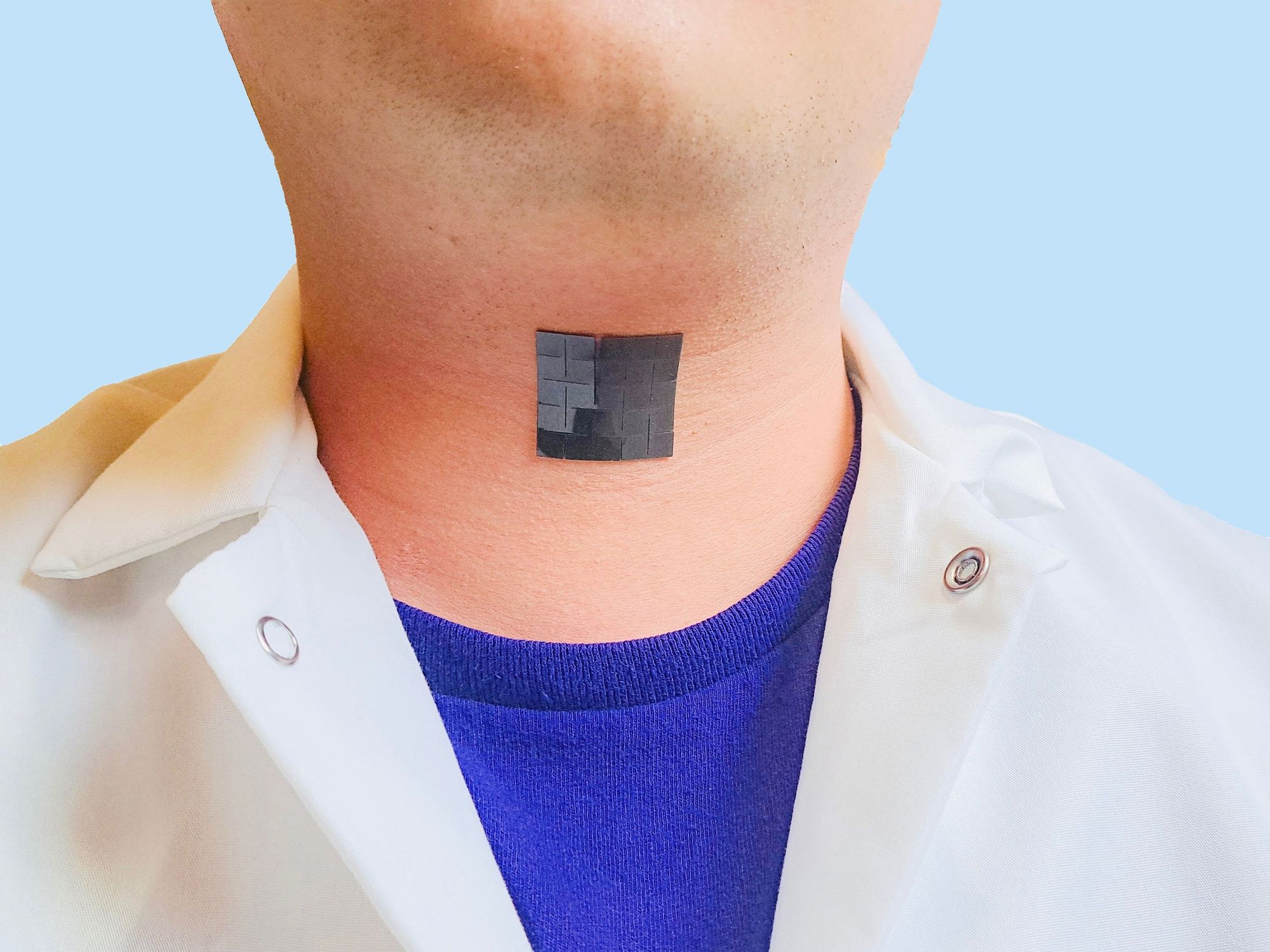
A new non-invasive wearable device provides one possible way to address this medical need. The technology consists of a lightweight patch adhered to a person’s neck, and that patch measures the person’s neck movements. Then an off-device processor translates those signals into speech, after which that speech audio is played out in lieu of the person’s voice.
“Similar to how the material converts muscle movements into electricity, it can also induce electricity as an input signal into mechanical vibrations in the device that produce sound.” —Jun Chen, UCLA
The research team, led by Jun Chen, assistant professor of biomedical engineering at UCLA, has created a flexible and electromagnetically responsive wearable that measures subtle neck muscle movements. A downstream device—not the sensing patch—then decodes the muscle movements the patch has sensed into speech, using a machine learning algorithm trained to recognize a set dictionary of phrases.
This technology could benefit people with injuries and diseases involving vocal fold paralysis, as well as those who have had surgeries like laryngectomies—removal of the larynx, which contains the vibrating muscles—that involve the removal of some or all of a person’s vocal folds.
The device’s performance is limited, however, by how many sentences it can play back. The present prototype AI model only selected from among five sentences: “Hi, how are you doing today?”; “Hope your experiments are going well!”; “Merry Christmas!”; “I love you!”; and “I don’t trust you.” The model was trained and tested on neck movements measured from people without any speech disability, who were asked to move their necks as though they were speaking but without vocalization.
Med tech options for voiceless
The new device joins other medical technologies that treat vocal fold disorders, such as prosthetic larynges and voice boxes, which vibrate the neck to recreate lost vocal fold movement. The UCLA patch approaches the problem differently, converting a user’s unvoiced neck muscle activity into computer-generated speech.
Dr. Barbara Messing, a clinical educator for medical device company Atos Medical and unaffiliated with the UCLA project, said the new approach is a welcome addition to the space of assistive speech devices: “The more things we can have that will help patients, the better,” said Messing. “Voice prostheses are the gold standard for patients that have had their larynx removed, but that isn’t every patient. Having more options for patients will only help with their quality of life, and that’s what we all want.”
To make its user’s unvocalized speech audible, the device passes the induced muscle movement signals to a machine learning model running on an external processor. This model is trained to detect patterns of muscle movement that correspond with a fixed number of predefined sentences. When it detects one of these phrases, the processor then plays the sentence back by vibrating the patch’s surface as a speaker. “Similar to how the material converts muscle movements into electricity,” says Chen, “it can also induce electricity as an input signal into mechanical vibrations in the device that produce sound.”
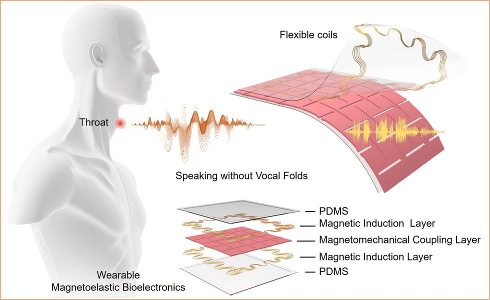 Researchers have developed an AI-powered vocalization patch that is non-invasively adhered to the throat. Thin magnetic induction coils and flexible magnetic materials in it then do the work to infer neck and throat movements beneath the skin. Jun Chen Lab/UCLA
Making the patch
The system’s throat patch applies new material science research from Chen’s group that takes advantage of a property called magnetoelasticity, in which the magnetic field strength of materials changes as the material is stretched and compressed. Regular, everyday activities and neck movements stretch the patch, resulting in magnetic field changes that are then measured by flexible inductive coils built in. These materials work in tandem to passively sense the minute, 3D movements of a user’s neck muscles.
While the magnetoelectric effect has been observed in metallic materials since the 19th century, the stiffness of such materials has made biological applications difficult—including measuring the contraction and expansion of a person’s neck muscles. Chen’s group has found a way to make very stretchy materials magnetoelastic by embedding particles of stiffer magnetoelastic materials into sheets of a flexible polymer.
The new magnetoelastic material’s flexibility lets it adhere to and accurately track the movement of the user’s neck muscles in a way that a similar sensor made from previously known magnetoelastic materials could not. To further enhance its sensitivity, the group shaped the material into a kirigami pattern—a papercraft similar to origami that permits cuts—that made the sensor behave evenly under smaller stretches and deflections.
Moving forward, Chen says the group will work on translating their research into a medical device. “In the future, we want to optimize the device and to standardize the fabrication procedure for mass production,” says Chen. “We have to improve the software and hardware, to increase the translation vocabulary and accuracy and make the device more user-friendly. All of these problems need to be solved, one-by-one.” Chen estimates the research group will produce a viable medical device “in 3-5 years.”
The researchers presented their findings earlier this month in the journal Nature Communications.
-
Exosuit Muscle Control Steps Closer to Reality

Exosuits—worn assistive frames that help users move their bodies—represent a promising technology that still has big challenges ahead. Not least of which is the fatigue problem. Specifically, exosuits that use electrical pulses to move a user’s muscles will quickly tire that user out. The fatigue problem has so far evaded a neat solution, but an international group of scientists is developing a new approach to the exosuit that could tackle fatigue via a system of controllably stiffening materials.
This set of technologies—toward a powered exoskeleton device the team is calling the Synapsuit—is the brainchild of researchers and engineers in South Korea and Switzerland. Their system is designed to sidestep the fatigue resulting from prolonged muscle stimulation—a technique also known as functional electrical stimulation (FES).
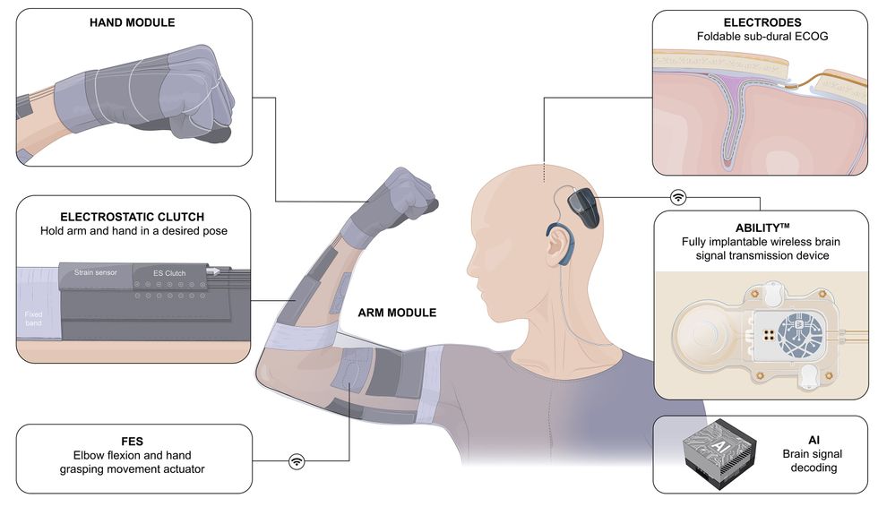 The Wyss team’s new electrostatic clutch promises to provide needed relief to electrically stimulated muscles. Wyss Center for Bio and Neuroengineering
Because FES is easy and cheap to implement and doesn’t require invasive surgery, it remains an attractive tool for assistive technologies. FES is currently used for physical therapy and rehabilitation, but the currents required to forcefully move a user’s body have generally proved too tiring on the muscles for prolonged use.
A new electrostatic clutch removes the need to continuously stimulate users’ muscles just to hold their joints in place.
The electrostatic clutch technology—currently being prototyped by the Korea Electronics Technology Institute (KETI) in Seongnam, South Korea—is a crucial component of the system’s design, the researchers say.
Kyuhwa Lee—machine learning scientist at the Wyss Center for Bio and Neuroengineering in Geneva and lead researcher on the Synapsuit project—says that this fatigue makes it hard to use FES systems throughout the day. “It cannot be used for the long term. To compensate for the fatigue,” Lee says, “we are using the electrostatic clutch system, so the user can maintain a fixed position.”
What’s an electrostatic clutch?
The Synapsuit’s electrostatic clutch system, the researchers say, is designed to hold a user’s joints in place between FES-driven movements. The clutches themselves are lightweight, flexible sleeves placed around the user’s elbows, wrists, and knuckles. These sleeves are normally clothlike and flexible but can be rapidly stiffened to support the joints they envelop between movements, thus removing the need to continuously stimulate the user’s muscles just to hold a joint in place.
The clutches stiffen when a voltage is applied to flexible conductive plates inside overlapping layers of material within the sleeve. “It’s like a capacitor,” says Lee. “When you apply a voltage, these materials pull toward each other and create a lot of friction.” The electrical force between the plates locks them in place with enough force to support, according to Lee, up to a 2-kilogram load. And when the potential is then lowered, the force between the layers goes away and the clutch returns to a flexible state.
Coordinating this dance between muscle stimulation and locking clutches requires fine and careful control—which is what the Synapsuit’s designers intend to be able to provide with the rest of their system.
Nitin Sharma, professor of mechanical and aerospace engineering at North Carolina State University, who is not affiliated with the research, says while he sees hope for the Synapsuit technologies, he sees plenty of room for improvement too.
“It’s a clever idea, for sure,” he says of the clutch technology. “What they haven’t shown is how the electrostatic clutch and electrical stimulation can work cooperatively. I see it will have benefits for reducing fatigue from FES, but how it will be used for cooperative control like stepping or reaching is unclear. I don’t think the clutch can do that, it’s only for holding position.”
 Ultimately, the researchers envision a neural interface for their Synapsuit assistive system.
Neurosoft
Ultimately, the researchers envision a neural interface for their Synapsuit assistive system.
Neurosoft
What’s next for the Synapsuit?
While the electrostatic clutch is being refined, another team is developing neural electrodes for ultimate use in controlling the Synapsuit.
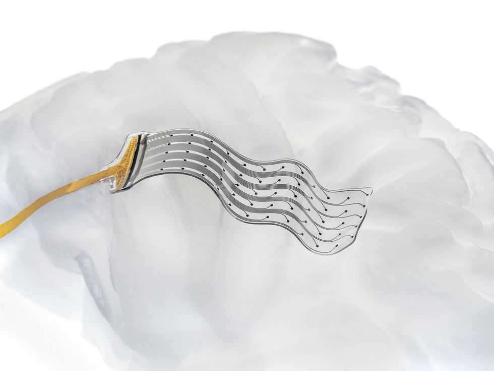
Developed by the Geneva-based Neurosoft Bioelectronics, the electrodes are now made from novel, stretchy materials that can conform to the brain’s lumpy ridges and folds, the researchers say. This sets them apart from other electrodes of this type which are relatively stiff and incapable of measuring neural activity from much of the brain’s highly wrinkled surface.
Nicolas Vachicouras, Neurosoft’s CEO, says its arrays are manufactured from highly flexible silicone using spin-coating techniques adopted from the semiconductor industry. Layer by layer, silicone and flexible conductive materials deposited onto a silicon wafer using automated processes very similar to those used to create the finicky architectures of microprocessors. “We didn’t reinvent new equipment, we just borrowed equipment typically used for something else,” says Vachicouras.
The conductive traces within the arrays were also designed to bend and stretch by making them out of “microcracked gold,” a material that maintains conductivity and stable electrical characteristics when bent out of shape. Vachicouras says that the team adopted part of the electrode from manufacturing processes developed for flexible display systems. “You never know where a technology’s going to end up,” Vachicouras says.
Don’t expect to put on the Synapsuit any time soon: while Neurosoft has begun human trials to test the system’s flexible neural electrodes, the KETI electrostatic clutch and neural-decoding software required to control the Synapsuit are still prototypes. Despite that, Lee says he expects the overall project to produce a functional Synapsuit system by 2026.
-
Pressure-Relief Eye Tech Advances Toward Approval
On 21 March, an advisory panel to the U.S. Food and Drug Administration gave its unanimous blessing to a piece of wearable technology that alleviates symptoms of the progressive eye disease glaucoma.
Known as the FSYX Ocular Pressure Adjusting Pump (OPAP) system, the device is designed to ease the pressure that accumulates in the eyes of people with glaucoma. This elevated pressure poses a risk of damaging the optic nerve, which relays visual information to the brain, leading to irreversible vision loss.
“This will give our toughest-to-treat patients additional options,” says John Berdahl, an ophthalmologist in Sioux Falls, S.D., and the founder of Balance Ophthalmics, the company developing the OPAP system.
Full regulatory approval is expected in the coming months. While the FDA is not required to adhere to its panels’ recommendations, it typically does so. According to Berdahl, Balance then plans to seek approval in other parts of the world. East Asia, a region with high incidences of the type of glaucoma addressed by the device, is a top priority, he says.
Pressure Point
Glaucoma remains a leading cause of blindness globally. Current treatment strategies include eye drops, laser treatments, and surgical procedures—but each has its limitations.
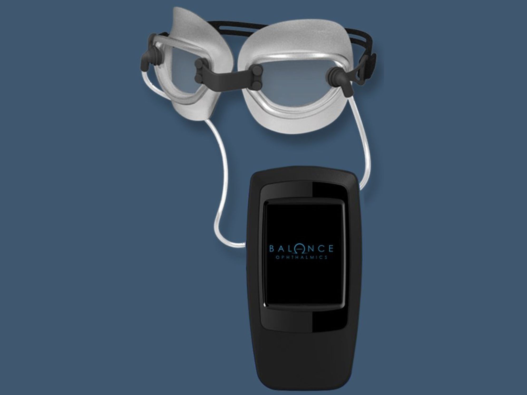
The OPAP system is designed for nighttime use, equipped with a programmable vacuum pump that delivers negative pressure to the eyes via a pair of snugly fitting goggles.
Eye drops can cause irritation, and they require diligent adherence. Surgery comes with the potential for infection, scarring, and other complications. And laser treatments cannot adequately reduce eye pressure in severe glaucoma cases.
What’s more, none of these interventions provide a quick fix to the ongoing challenge of maintaining proper pressure within the eyeball—what clinicians refer to as intraocular pressure (IOP).
“The biggest void that we have currently in glaucoma care is the ability to instantaneously modify a patient’s IOP,” says Brian Shafer, an ophthalmologist in Plymouth Meeting, Pa.
The wearable OPAP device thus offers a much-needed alternative, one that can be dialed in to the specific pressure needs of each glaucoma patient.
With this setup, “you’ve got this super-modifiable, titratable, instantaneous method to adjust IOP—and we don’t have that with anything else,” says Shafer, who consulted for a now-defunct precursor company to Balance.
If it receives FDA go-ahead, OPAP would become the first nonsurgical, nonpharmacological, purely physics-based treatment option for glaucoma—in particular, for a form of the disease known as “normal-tension glaucoma” in which IOP is not raised outside of typical levels yet the pressure wreaks havoc on the optic nerve nonetheless.
Transforming the Negative
According to Balance CEO Seph Jensen, the company chose the name OPAP to mirror the functionality of CPAP machines, which assist individuals with obstructive sleep apnea.
In line with those sleep-apnea devices, the OPAP system is designed for nighttime use and is equipped with a programmable vacuum pump that delivers negative pressure to the eyes via a pair of snugly fitting goggles.
This negative pressure is thought to modify fluid dynamics within the eye and its supporting blood vessels. Those changes in turn help to limit mechanical strain on the optic nerve head, the funnel through which more than a million nerve fibers from the retina come together to transmit visual signals to the brain.
“And basically,” says Ross Ethier, a bioengineer at Georgia Tech who consults for Balance and has modeled these effects, “everything we know about glaucoma tells us that that will be beneficial for patients if they wear the device.”
Published experiments with cadavers and brain-dead organ donors—individuals who have consented to allowing such research studies—largely bear this out. (The cadaver study, it should be noted, was funded by Balance’s predecessor company, although the organ-donor study was funded by foundation and government grants.)
In cadavers, for example, Shafer found that the negative pressure exerted by the OPAP system altered pressure within the eye, but did not change pressures further back in areas leading toward the brain. This normalization of the pressure gradient across the back of eye is thought to help stop the damage that can lead to glaucoma.
“It proved that the theory behind it actually works,” Shafer says.
Moreover, in a yearlong clinical trial, around 90 percent of people who wore the goggles nightly experienced a dramatic drop in IOP in their treated eyes, with no major safety issues. (The most common side effect was mild swelling in the eyelids or surrounding tissue.) By comparison, less than 5 percent of control eyes achieved this same pressure reduction on their own.
The 93-person trial was not designed to test the device’s ability to forestall visual impairment—the primary concern for individuals with glaucoma. However, says Jeffrey Goldberg, an ophthalmologist at Stanford University who led an earlier pilot study, “reducing nighttime eye pressure is highly likely to protect patients with glaucoma from vision loss over time.”
Berdahl and his clinical collaborators presented the unpublished trial data at the 21 March FDA online advisory committee meeting.
Goggle Glitches
As it currently stands, the device does not meet the FDA’s latest cybersecurity standards. That means users will have to physically connect their goggles via USB cable to upload data in a clinician’s office.
Data tracking is essential for patient compliance, insurance reimbursement, and aiding in disease management, says the company. In the future, Balance hopes to release a Bluetooth-connected version that can securely transmit user information to the cloud.
The OPAP system is more like a CPAP machine than its inventors necessarily anticipated. Both seem to be highly effective—but only if worn correctly and consistently.
Another limitation: the goggles can make people uncomfortable as they sleep. Just ask Joseph Kim.
“I couldn’t handle the therapy,” he says.
Kim has long worked in the clinical-trial arena, helping to optimize the experience for patients and to streamline protocol tasks for study investigators. So when, shortly after being diagnosed with glaucoma, Kim was invited to participate in a trial for the OPAP system, he went for it. “I jumped at the chance,” he says.
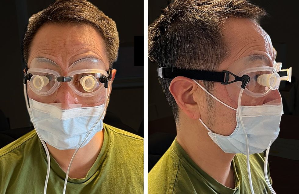 Test patient Joseph Kim has tried out the OPAP device for nighttime relief of his glaucoma symptoms. Joseph Kim
Kim says he didn’t mind applying eye drops each night. But the OPAP trial promised more than just treatment; it offered a window into the patient’s journey through the eyes of a participant.
“It seemed like a great way to get more firsthand knowledge about the patient experience in an honest way,” says Kim, chief strategy officer for ProofPilot, a company that develops software to support medical trials.
He says he struggled with the device, though. Kim normally sleeps on his side, but doing so often jostled his goggles, breaking the pressure seal, and triggering alarms that would wake him up. Sweat would also build up under the goggles, causing irritation and unease.
Faced with consecutive nights of poor sleep, Kim—like around one-third of all participants who started with the OPAP system in its pivotal clinical test—made the decision to withdraw from the trial.
“Listen, I’m in the business of clinical research,” he says, “and I just couldn’t do it—sadly.”
In this way, the OPAP system is more like a CPAP machine than its inventors necessarily anticipated. Both seem to be highly effective—but only if worn correctly and consistently. And many would-be beneficiaries could have trouble with device tolerance.
Therefore, says Toh Song Tar, a sleep-apnea specialist at Singapore General Hospital who has studied the connections between apnea and glaucoma, “patient counseling will be important.”
“If people understand that the OPAP device will help to protect their eyesight against the ill effects of glaucoma, it will help and they will be more diligent in using it,” he says.
The success of the OPAP system, potentially the first wearable technology for glaucoma care, could therefore depend less on the technical aspects of applying negative pressure to the eye, which has been the focus of Berdahl’s research for the past decade.
Instead, it could hinge on an unpredictable factor: human behavior and the willingness of glaucoma patients to stick with the technology.
-
Here Are 6 Actual Uses for Near-Term Quantum Computers
Although recent findings have poured cold water on quantum computing hype, don’t count the technology out yet. On 4 March, Google and XPrize announced a US $5 million prize to anyone who comes up with use cases for quantum computers. If that sounds like an admission that use cases don’t already exist, it isn’t, says Ryan Babbush, head of quantum algorithms at Google. “We do know of some applications that these devices would be quite impactful for,” he says.
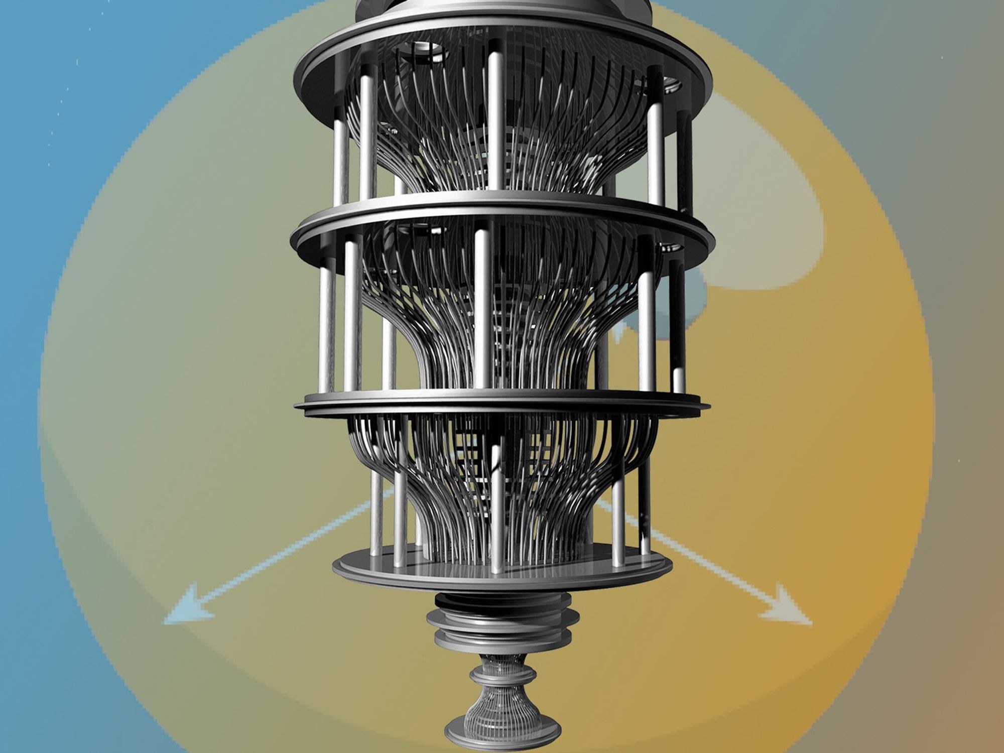
“A quantum computer is a special purpose accelerator,” says Matthias Troyer, corporate vice president of Microsoft Quantum and member of the Xprize competition’s advisory board. “It can have a huge impact for special problems where quantum mechanics can help you solve them.”
The kinds of problems for which quantum computers could be useful hark back to their historical roots. In 1981, physicist Richard Feynman proposed the idea of a quantum computer as a means of simulating the full complexity of the quantum world.
“The commercial impact of solving quantum systems is in chemistry, material science, and pharma.” —Matthias Troyer, Microsoft Quantum
Since then, scientists have come up with ingenious algorithms to make quantum computers useful for non-quantum things, such as searching databases or breaking cryptography. However, the database search algorithms don’t promise viable speedups in the foreseeable future, and destroying Internet security seems like a dubious reason to build a new machine. But a recent study suggests that quantum computers will be able to simulate quantum phenomena of interest to several industries well before they can make headway in those other applications.
“The commercial impact of solving quantum systems is in chemistry, material science, and pharma,” Troyer says. And these are industries of significance, Troyer adds. “From the Stone Age to the Bronze Age, the Iron Age, the Steel Age, the Silicon Age, we define progress through materials progress.”
On that path to the possible new Quantum Age, here are a few examples with proven quantum advantage on machines that quantum computing researchers expect within the coming decade. And with any luck, Troyer hopes that the $5 million prize will incentivize the scientific community to find even more ways to put quantum algorithms to use in the real world. “The goal [of the prize] is that we want to have more quantum scientists get interested in not just developing quantum algorithms and the theory of them but also asking: Where can they be applied? How can we use quantum computers to tackle the world’s big problems?”
Drug Metabolism
In a 2022 paper published in PNAS, a collaboration between pharmaceutical company Boehringer Ingelheim, Columbia University, Google Quantum AI, and quantum simulation company QSimulate examined an enzyme called cytochrome P450. This particular enzyme is responsible for metabolizing roughly 70 percent of the drugs that enter the human body. The oxidation process by which the enzyme metabolizes drugs is inherently quantum, in a way that is difficult to simulate classically (classical methods work well when there are not a lot of quantum correlations at different scales).
They found that a quantum computer of a few million qubits would be able to simulate the process faster and more precisely than state-of-the-art classical techniques. “We find that the higher accuracy offered by a quantum computer is needed to correctly resolve the chemistry in this system, so not only will a quantum computer be better, it will be necessary,” the researchers (including Babbush) wrote in a blog post.
CO2 Sequestration
One strategy to lower the amount of carbon dioxide in the atmosphere is sequestration—using a catalyst to react with the carbon dioxide and form a compound that can be stored for a long time. Sequestration strategies exist, but are not cost or energy efficient enough to make a significant dent in the current carbon emissions.
Several recent studies have suggested that quantum computers of the near future should be able to model carbon dioxide reactions with various catalysts more accurately than classical computers. If true, this would allow scientists to more effectively estimate the efficiency of various sequestration candidates.
Agricultural Fertilization
Most farmland today is fertilized with ammonia produced under high temperature and pressure in large plants via the Haber-Bosch process. In 2017, a team at Microsoft Research and ETH Zurich considered an alternative ammonia production method—nitrogen fixation by way of the enzyme nitrogenase—that would work at ambient temperature and pressure.
This reaction cannot be accurately simulated by classical methods, the researchers showed, but it is within the reach of a classical and quantum computer working in tandem. “If, for example, you could find a chemical process for nitrogen fixation is a small scale in a village on a farm, that would have a huge impact on the food security,” says Troyer, who was involved in the research.
Alternate Battery Cathodes
Many lithium-ion batteries use cobalt in their cathodes. Cobalt mining has some practical drawbacks, including environmental concerns and unsafe labor practices. One alternative to cobalt is nickel. In a study published in 2023, a collaboration between chemical producer BASF, Google Quantum AI, Macquarie University in Sydney, and QSimulate considered what it would take to simulate a nickel-based cathode, lithium nickel oxide, on a quantum computer.
Pure lithium nickel oxide, the researchers said, is unstable in production, and its basic structure is poorly understood. Having a better simulation of the material’s ground state may suggest methods for making a stable version. The quantum computing requirements to adequately simulate this problem are “out of reach of the first error-corrected quantum computers,” the authors wrote in a blog post, “but we expect this number to come down with future algorithmic improvements.”
Fusion Reactions
In 2022, the National Ignition Facility made headlines with the first inertial fusion reaction to produce more energy than was put directly into it. In an inertial fusion reaction, a tritium-deuterium mixture is heated with lasers until it forms a plasma that collapses into itself, initiating the fusion reaction. This plasma is extremely difficult to simulate, says Babbush, who was involved with the study. “The Department of Energy is already spending hundreds of millions of CPU hours if not billions of CPU hours, just computing one quantity,” he says.
In a preprint, Babbush and his collaborators outlined an algorithm that a quantum computer could use to model the reaction in its full complexity. This, like the battery cathode research, would require more qubits than are currently available, but the authors believe future hardware and algorithmic improvements may close this gap.
Improving Quantum Sensors
Unlike quantum computers, quantum sensors are already having an impact in the real world. These sensors can measure magnetic fields more precisely than any other technology, and are being used for brain scans, gravity measurements for mapping geological activity, and more. The output of the quantum sensor is quantum data, but it’s currently read out as classical data, traditional ones and zeros that miss some of the full quantum complexity.
A 2022 study from a collaboration between Google, Caltech, Harvard, UC Berkeley, and Microsoft has shown that if the output of a quantum sensor is instead funneled into a quantum computer, they can use a clever algorithm to learn relevant properties with exponentially fewer copies of the data from the sensor, speeding up readout. They demonstrated their quantum algorithm on a simulated sensor, showing that this algorithms is within reach for even currently existing quantum computers.
And More
There are also advantageous quantum algorithms still in search of definitive use cases, and prize money is being offered to also motivate that search. Among those algorithms are solving certain types of linear differential equations, and finding patterns in data that are not accessible classically. In addition, classically, many algorithms can’t be proven to work efficiently with pencil and paper, says Jay Gambetta, vice president at IBM Quantum. Instead, people try heuristic algorithms out on real hardware, and some of them perform surprisingly well. With quantum computers, Gambetta argues, the hardware state of the art is on the cusp of being good enough to test out many more heuristic algorithms, so many more use cases should be forthcoming.
“I think we can finally start to do algorithm discovery using hardware,” Gambetta says. “And to me that’s opening a different avenue for accelerated scientific discovery. And I think that’s what’s most exciting.”
-
Electroadhesion Heralds New Implant and Robot Tech

Applying electricity for a few seconds to a soft material, such as a slice of raw tomato or chicken, can strongly bond it to a hard object, such as a graphite slab, without any tape or glue, a new study finds. This unexpected effect is also reversible—switching the direction of the electric current often easily separates the materials, scientists at the University of Maryland say. Potential applications for such “electroadhesion,” which can even work underwater, may include improved biomedical implants and biologically inspired robots.
“It is surprising that this effect was not discovered earlier,” says Srinivasa Raghavan, a professor of chemical and biomolecular engineering at the University of Maryland. “This is a discovery that could have been made pretty much since we’ve had batteries.”
In nature, soft materials such as living tissues are often bonded to hard objects such as bones. Previous research explored chemical ways to accomplish this feat, such as with glues that mimic how mussels stick to rocks and boats. However, these bonds are usually irreversible.
They tried a number of different soft materials, such as tomato, apple, beef, chicken, pork and gelatin...
Previously, Raghavan and his colleagues discovered that electricity could make gels stick to biological tissue, a discovery that might one day lead to gel patches that can help repair wounds. In the new study, instead of bonding two soft materials together, they explored whether electricity could make a soft material stick to a hard object.
The scientists began with a pair of graphite electrodes (consisting of an anode and a cathode) and an acrylamide gel. They applied five volts across the gel for three minutes. Surprisingly, they found the gel strongly bonded onto the graphite anode. Attempts to wrench the gel and electrode apart would typically break the gel, leaving pieces of it on the electrode. The bond could apparently last indefinitely after the voltage was removed, with the researchers keeping samples of gel and electrode stuck together for months.
Howeve, when the researchers switched the polarity of the current, the acrylamide gel detached from the anode. Instead, it adhered onto the other electrode.
Raghavan and his colleagues experimented with this newfound electroadhesion effect a number of different ways. They tried a number of different soft materials, such as tomato, apple, beef, chicken, pork and gelatin, as well as different electrodes, such as copper, lead, tin, nickel, iron, zinc and titanium. They also varied the strength of the voltage and the amount of time it was applied.
The researchers found the amount of salt in the soft material played a strong role in the electroadhesion effect. The salt makes the soft material conductive, and high concentrations of salt could lead gels to adhere to electrodes within seconds.
“It’s surprising how simple this effect is, and how widespread it might be”
The scientists also discovered that metals that are better at giving up their electrons, such as copper, lead and tin, are better at electroadhesion. Conversely, metals that hold onto their electrons strongly, such as nickel, iron, zinc and titanium, fared poorly.
These findings suggest that electroadhesion arises from chemical bonds between the electrode and soft material after they exchange electrons. Depending on the nature of the hard and soft materials, adhesion happened at the anode, cathode, both electrodes, or neither. Boosting the strength of the voltage and the amount of time it was applied typically increased adhesion strength.
“It’s surprising how simple this effect is, and how widespread it might be,” Raghavan says.
Potential applications for electroadhesion may include improving biomedical implants—the ability to bond tissue to steel or titanium could help reinforce implants, the researchers say. Electroadhesion may also help create biologically inspired robots with stiff bone-like skeletons and soft muscle-like elements, they add. They also suggest electroadhesion could lead to new kinds of batteries where soft electrolytes are bonded to hard electrodes, although it’s not clear if such adhesion would make much of a difference to a battery’s performance, Raghavan says.
The researchers also discovered that electroadhesion could occur underwater, which they suggest could open up an even wider range of possible applications for this effect. Typical adhesives do not work underwater, since many cannot spread onto solid surfaces that are submerged in liquids, and even those that can usually only form weak adhesive bonds due to interference from the liquid.
“It’s hard for me to pinpoint one real application for this discovery,” Raghavan says. “It reminds me of the researchers who made the discoveries behind Velcro or Post-it notes—the applications were not obvious to them when the discoveries were made, but the applications did arise over time.”
The scientists detailed their findings online 13 March in the journal ACS Central Science.
-
Stretchy Circuits Break Records for Flexible Electronics

Newly developed intrinsically stretchable circuits are thousands of times as fast as and possess 20 times as many transistors as previous intrinsically stretchable electronics. The researchers at Stanford University who developed the circuits have already demonstrated their use in a skin-like Braille-reading sensor array that they say is more sensitive than a human fingertip.
In general, flexible electronics have potential for any application requiring interactions with soft materials, such as devices worn on or implanted within the body. Those applications could include on-skin computers, soft robotics, and brain-machine interfaces.
However, conventional electronics are made of rigid materials such as silicon and metal. Placing electronic components on plastic films can make them flexible enough to bend; however, the extent to which such devices can stretch is typically just about 1 percent of their normal size, says Zhenan Bao, a professor of chemical engineering at Stanford University.
Previous research has explored how to create electronics from intrinsically stretchable materials such as carbon nanotubes and silver nanowires. But until now stretchable electronics have shown dismal performance.
Bao and her colleagues have now developed intrinsically stretchable transistors and circuits that have set multiple new records. They published their findings on 13 March in the journal Nature.
“Stretchable sensor arrays can be incorporated into prosthetic limbs and orthopedic devices to provide feedback on pressure distribution, muscle activity, and joint movements.” —Zhenan Bao, Stanford University
The new devices feature high-purity semiconducting carbon nanotube channels, metallic palladium-coated carbon nanotube electrodes, and high-conductivity stretchable gallium-indium alloy interconnects. A major goal of the design was to reduce factors such as parasitic capacitance and interconnect resistance that limit transistor speed.
The researchers fabricated an integrated circuit about 28 square millimeters in size that possesses 1,056 transistors, 528 logic gates, and an operating speed of more than 1 megahertz. Previous intrinsically stretchable electronics were at best capable of 54 transistors and 14 logic gates per circuit, and operating speeds of only 330 hertz.
In addition, the new stretchable transistors demonstrated a field-effect mobility—the speed at which charge flows in a device, which helps control transistor switching speed—of more than 20 square centimeters per volt per second on average, even when stretched to twice their normal size. This results in electrical performance about 20 times as good as previous stretchable electronics, the researchers say.
The transistors also displayed a drive current—which also influences transistor switching speed—of about 2 milliamps per micron, given a supply voltage of 5 volts. This is more than 40 times better than prior stretchable devices. All in all, these new transistors perform roughly as well as state-of-the-art flexible transistors that combine carbon nanotubes, metal oxides, or polycrystalline silicon with plastic films.
To demonstrate a practical application for the new electronics, the researchers built an 8-square-millimeter tactile sensor array that could stick onto a human finger and read Braille writing. The array’s pixels are each just 200 microns wide and arranged in a 10 by 20 pixel grid. In other words, the array posses 2,500 sensors per square centimeter, which is more than 10 times the density of a human fingertip’s mechanical receptors.
The array’s dense configuration of sensors makes it possible to recognize shapes such as triangles, circles, and rectangles less than 1 millimeter across. “Stretchable sensor arrays can be incorporated into prosthetic limbs and orthopedic devices to provide feedback on pressure distribution, muscle activity, and joint movements,” Bao says. “Stretchable sensor arrays can also be used in human-machine interfaces for gesture recognition and motion tracking.”
The new electronics could also help drive an LED array with a refresh rate of more than 60 Hz, which is typical of a computer or TV screen. Even when twisted or stretched, the transistor array could still display numbers, letters, and symbols. One possible application this would enable are stretchable displays for wearable devices that “can conform to the contours of the body, providing users with real-time information and notifications while maintaining comfort without constraining daily life,” Bao says.
The new circuits are made with materials and processes that can work with existing fabrication methods. Bao notes that industry manufacturers cannot make the new circuits without some additional fine-tuning of their fabrication processes, but the tools are already in place.
One future direction for research is to find better ways of packaging the electronics. This will help enable stable operation and long life, Bao says.
-
How Ultrasound Became Ultra Small
A startling change in medical ultrasound is working its way through hospitals and physicians’ offices. The long-standing, state-of-the-art ultrasound machine that’s pushed around on a cart, with cables and multiple probes dangling, is being wheeled aside permanently in favor of handheld probes that send images to a phone.
These devices are small enough to fit in a lab coat pocket and flexible enough to image any part of the body, from deep organs to shallow veins, with sweeping 3D views, all with a single probe. And the AI that accompanies them may soon make these devices operable by untrained professionals in any setting—not just trained sonographers in clinics.
The first such miniaturized, handheld ultrasound probe arrived on the market in 2018, from
Butterfly Network in Burlington, Mass. Last September, Exo Imaging in Santa Clara, Calif., launched a competing version.
Making this possible is silicon ultrasound technology, built using a type of microelectromechanical system (MEMS) that crams 4,000 to 9,000 transducers—the devices that convert electrical signals into sound waves and back again—onto a 2-by-3-centimeter silicon chip. By integrating MEMS transducer technology with sophisticated electronics on a single chip, these scanners not only replicate the quality of traditional imaging and 3D measurements but also open up new applications that were impossible before.
How does ultrasound work?
To understand how researchers achieved this feat, it’s helpful to know the basics of ultrasound technology. Ultrasound probes use transducers to convert electrical energy to sound waves that penetrate the body. The sound waves bounce off the body’s soft tissue and echo back to the probe. The transducer then converts the echoed sound waves to electrical signals, and a computer translates the data into an image that can be viewed on a screen.
Conventional ultrasound probes contain transducer arrays made from slabs of piezoelectric crystals or ceramics such as lead zirconium titanate (PZT). When hit with pulses of electricity, these slabs expand and contract and generate high-frequency ultrasound waves that bounce around within them.
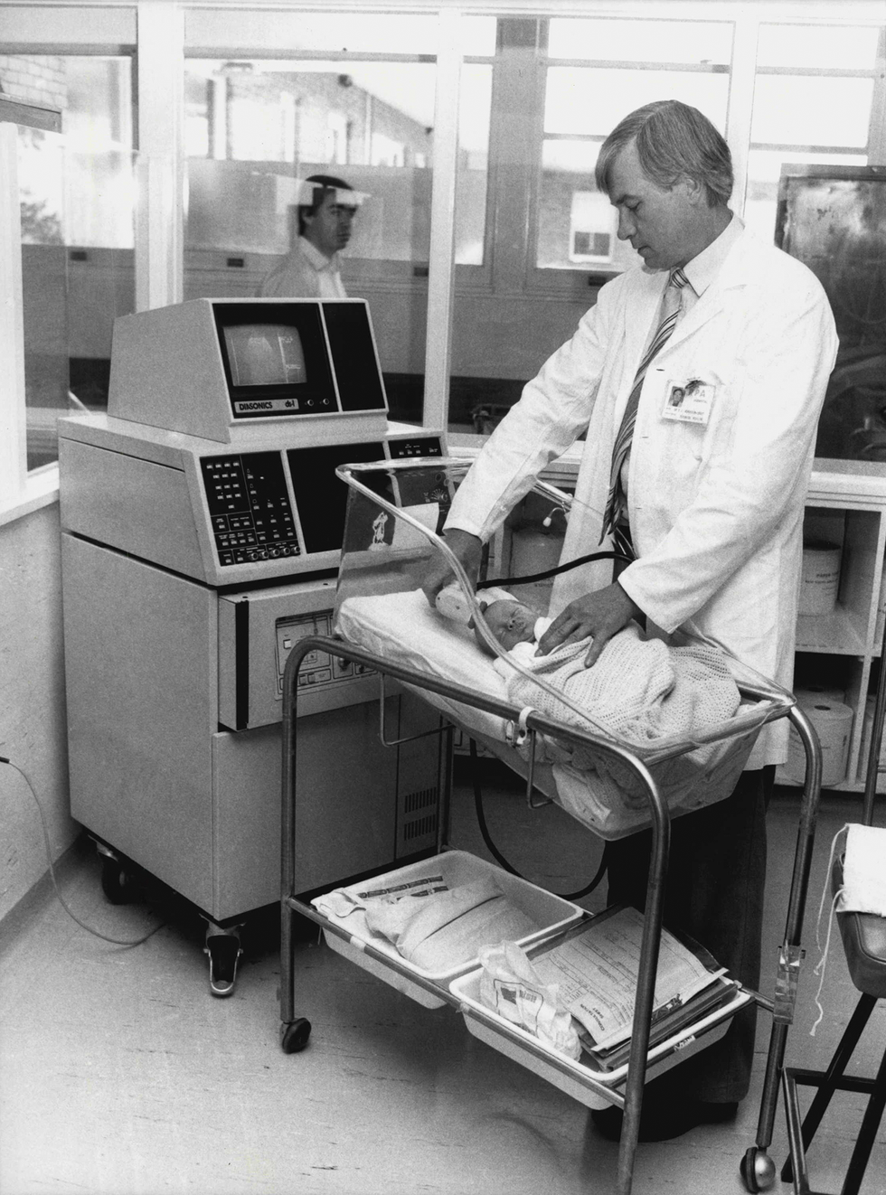 Ultrasound technology has historically required bulky machinery with multiple probes. Julian Kevin Zakaras/Fairfax Media/Getty Images
To be useful for imaging, the ultrasound waves need to travel out of the slabs and into the soft tissue and fluid of the patient’s body. This is not a trivial task. Capturing the echo of those waves is like standing next to a swimming pool and trying to hear someone speaking under the water. The transducer arrays are thus built from layers of material that smoothly transition in stiffness from the hard piezoelectric crystal at the center of the probe to the soft tissue of the body.
The frequency of energy transferred into the body is determined mainly by the thickness of the piezoelectric layer. A thinner layer transfers higher frequencies, which allow smaller, higher-resolution features to be seen in an ultrasound image, but only at shallow depths. The lower frequencies of thicker piezoelectric material travel further into the body but deliver lower resolutions.
As a result, several types of ultrasound probes are needed to image various parts of the body, with frequencies that range from 1 to 10 megahertz. To image large organs deep in the body or a baby in the womb, physicians use a 1- to 2-MHz probe, which can provide 2- to 3-millimeter resolution and can reach up to 30 cm into the body. To image blood flow in arteries in the neck, physicians typically use an 8- to 10-MHz probe.
How MEMS transformed ultrasound
The need for multiple probes along with the lack of miniaturization meant that conventional medical ultrasound systems resided in a heavy, boxy machine lugged around on a cart. The introduction of MEMS technology changed that.
Over the last three decades MEMS has allowed manufacturers in an
array of industries to create precise, extremely sensitive components at a microscopic scale. This advance has enabled the fabrication of high-density transducer arrays that can produce frequencies in the full 1- to 10-MHz range, allowing imaging of a wide range of depths in the body, all with one probe. MEMS technology also helped miniaturize additional components so that everything fits in the handheld probe. When coupled with the computing power of a smartphone, this eliminated the need for a bulky cart.
The first MEMS-based silicon ultrasound prototypes emerged in the mid-1990s when the excitement of MEMS as a new technology was peaking. The key element of these early transducers was the vibrating micromachined membrane, which allowed the devices to generate vibrations in much the same way that banging on a drum creates sound waves in the air.
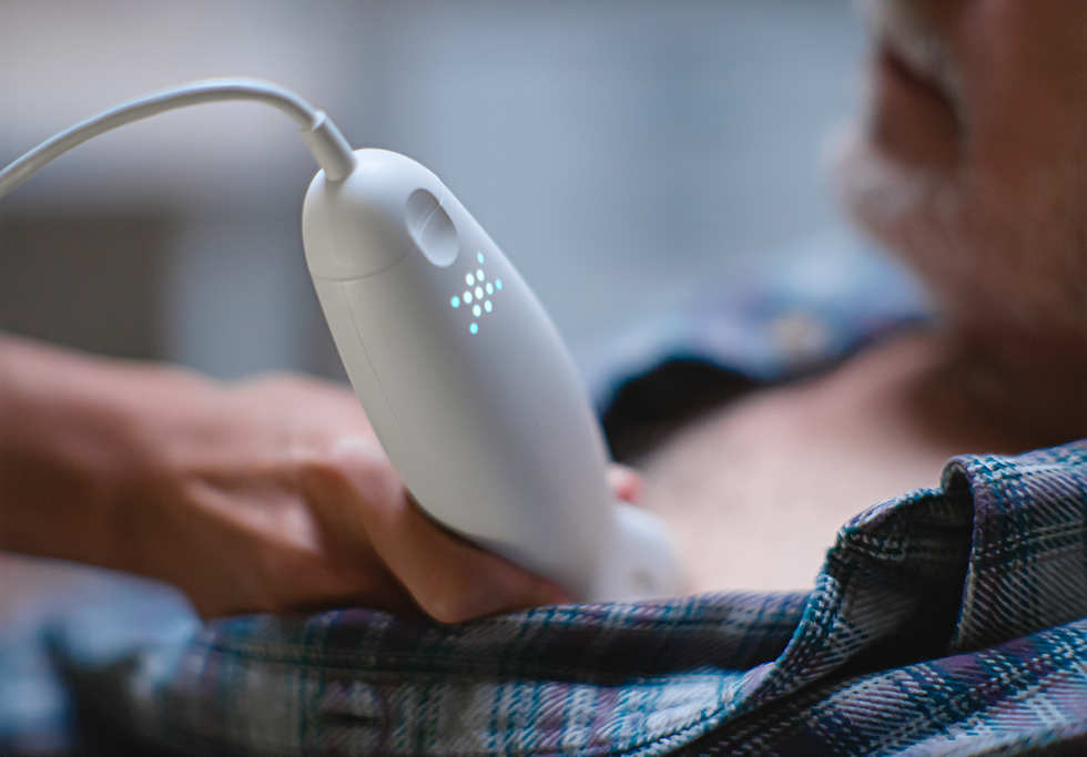
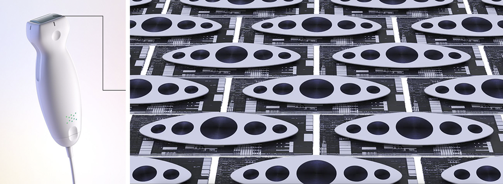 Exo Imaging developed a handheld ultrasound machine using piezoelectric micromachined ultrasonic transducer (PMUT) technology.Exo Imaging
Two architectures emerged. One of them, called the
capacitive micromachined ultrasonic transducer, or CMUT, is named for its simple capacitor-like structures. Stanford University electrical engineer Pierre Khuri-Yakub and colleagues demonstrated the first versions.
The CMUT is based on electrostatic forces in a capacitor formed by two conductive plates separated by a small gap. One plate—the micromachined membrane mentioned before—is made of silicon or silicon nitride with a metal electrode. The other—typically a micromachined silicon wafer substrate—is thicker and more rigid. When a voltage is applied, placing opposite charges on the membrane and substrate, attractive forces pull and flex the membrane toward the substrate. When an oscillating voltage is added, that changes the force, causing the membrane to vibrate, like a struck drumhead.
When the membrane is in contact with the human body, the vibrations send ultrasound frequency waves into the tissue. How much ultrasound is generated or detected depends on the gap between the membrane and the substrate, which needs to be about one micrometer or less. Micromachining techniques made that kind of precision possible.
The other MEMS-based architecture is called the
piezoelectric micromachined ultrasonic transducer, or PMUT, and it works like a miniaturized version of a smoke alarm buzzer. These buzzers consist of two layers: a thin metal disk fixed around its periphery and a thin, smaller piezoelectric disk bonded on top of the metal disk. When voltages are applied to the piezoelectric material, it expands and contracts in thickness and from side to side. Because the lateral dimension is much larger, the piezo disk diameter changes more significantly and in the process bends the whole structure. In smoke alarms, these structures are typically 4 cm in diameter, and they’re what generates the shrieking sound of the alarm, at around 3 kilohertz. When the membrane is scaled down to 100 μm in diameter and 5 to 10 μm in thickness, the vibration moves up into megahertz frequencies, making it useful for medical ultrasound.
Honeywell in the early 1980s developed the first micromachined sensors using piezoelectric thin films built on silicon diaphragms. The first PMUTs operating at ultrasound frequencies didn’t emerge until
1996, from the work of materials scientist Paul Muralt at the Swiss Federal Institute of Technology Lausanne (EPFL), in Switzerland.
Early years of CMUT
A big challenge with CMUTs was getting them to generate enough pressure to send sound waves deep into the body and receive the echoes coming back. The membrane’s motion was limited by the exceedingly small gap between the membrane and the substrate. This constrained the amplitude of the sound waves that could be generated. Combining arrays of CMUT devices with different dimensions into a single probe to increase the frequency range also compromised the pressure output because it reduced the probe area available for each frequency.
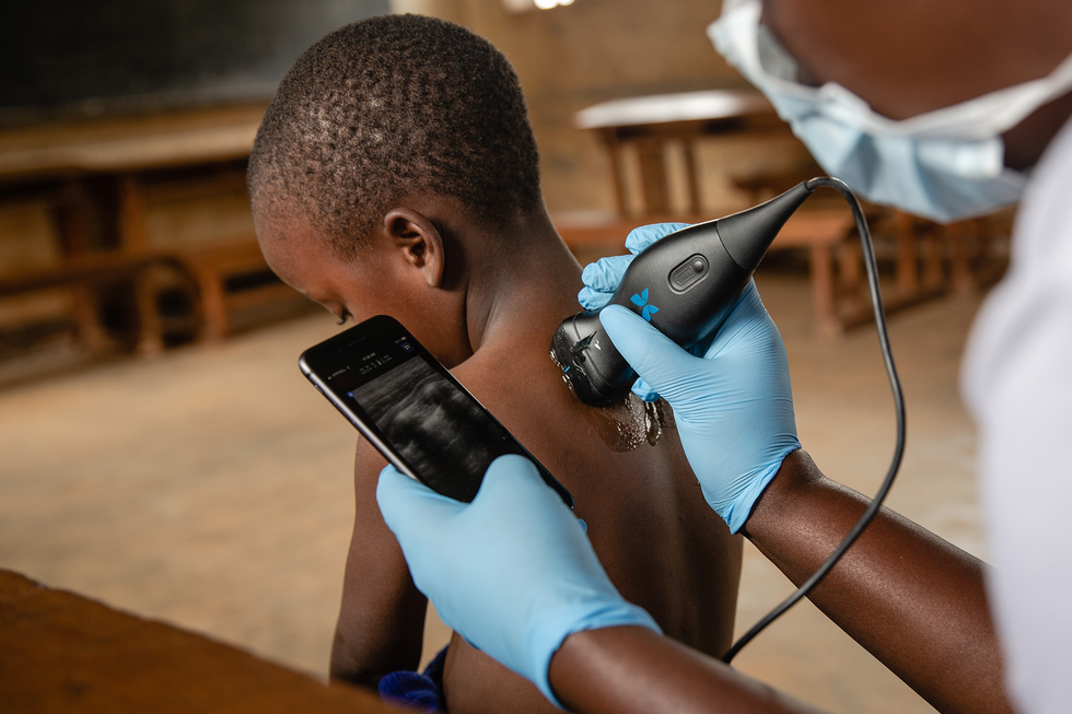 Butterfly Network developed a handheld ultrasound machine using capacitive micromachined ultrasonic transducer (CMUT) technology.Butterfly
The solution to these problems came from Khuri-Yakub’s lab at Stanford University. In
experiments in the early 2000s, the researchers found that increasing the voltage on CMUT-like structures caused the electrostatic forces to overcome the restoring forces of the membrane. As a result, the center of the membrane collapses onto the substrate.
A collapsed membrane seemed disastrous at first but turned out to be a way of making CMUTs both more efficient and more tunable to different frequencies. The efficiency increased because the gap around the contact region was very small, increasing the electric field there. And the pressure increased because the large doughnut-shaped region around the edge still had a good range of motion. What’s more, the frequency of the device could be adjusted simply by changing the voltage. This, in turn, allowed a single CMUT ultrasound probe to produce the entire ultrasound frequency range needed for medical diagnostics with high efficiency.
Inside Butterfly Network’s CMUT ultrasound probe, the membrane collapses onto the substrate, generating an acoustic wave.Butterfly Network
From there, it took more than a decade to understand and model the complicated electromechanical behavior of CMUT arrays and iron out the manufacturing. Modeling these devices was tricky because thousands of individual membranes interacted in each CMUT array.
On the manufacturing side, the challenges involved finding the right materials and developing the processes needed to produce smooth surfaces and a consistent gap thickness. For example, the thin dielectric layer that separates the conductive membrane and the substrate must withstand about 100 volts at a thickness of 1 μm. If the layer has defects, charges can be injected into it, and the device can short at the edges or when the membrane touches the substrate, killing the device or at least degrading its performance.
Eventually, though, MEMS foundries such as Philips Engineering Solutions in Eindhoven, Netherlands, and Taiwan Semiconductor Manufacturing Co. (TSMC), in Hsinchu, developed solutions to these problems. Around 2010, these companies began producing reliable, high-performance CMUTs.
Early development of PMUTs
Early PMUT designs also had trouble generating enough pressure to work for medical ultrasound. But they could bang out enough to be useful in some consumer applications, such as
gesture detection and proximity sensors. In such “in-air ultrasound” uses, bandwidth isn’t critical, and frequencies can be below 1 MHz.
In 2015, PMUTs for medical applications got an unexpected boost with the introduction of large 2D matrix arrays for fingerprint sensing in mobile phones. In the first demonstration of this approach, researchers at the University of California, Berkeley, and the University of California, Davis, connected around 2,500 PMUT elements to CMOS electronics and placed them under a silicone rubberlike layer. When a fingertip was pressed to the surface, the prototype measured the amplitudes of the reflected signals at 20 MHz to distinguish the ridges in the fingertip from the air pockets between them.
This was an impressive demonstration of integrating PMUTs and electronics on a silicon chip, and it showed that large 2D PMUT arrays could produce a high enough frequency to be useful for imaging of shallow features. But to make the jump to medical ultrasound, PMUT technology needed more bandwidth, more output pressure, and piezoelectric thin films with better efficiency.
Help came from semiconductor companies such as
ST Microelectronics, based in Geneva, which figured out how to integrate PZT thin films on silicon membranes. These films require extra processing steps to maintain their properties. But the improvement in performance made the cost of the extra steps worthwhile.
To achieve a larger pressure output, the piezoelectric layer needed to be thick enough to allow the film to sustain the high voltages required for good ultrasound images. But increased thickness leads to a more rigid membrane, which reduces the bandwidth.
One solution was to use an oval-shaped PMUT membrane that effectively combined several membranes of different sizes into one. This is similar to changing the length of guitar strings to generate different tones. The oval membrane provides strings of multiple lengths on the same structure with its narrow and wide sections. To efficiently vibrate wider and narrower parts of the membrane at different frequencies, electrical signals are applied to multiple electrodes placed on corresponding regions of the membrane. This approach allowed PMUTs to be efficient over a wider frequency range.
From academia to the real world
In the early 2000s, researchers began to push CMUT technology for medical ultrasound out of the lab and into commercial development. Stanford University spun out several startups aimed at this market. And leading medical ultrasound imaging companies such as GE, Philips, Samsung, and Hitachi began developing CMUT technology and testing CMUT-based probes.
But it wasn’t until 2011 that CMUT commercialization really began to make progress. That year, a team with semiconductor electronics experience founded Butterfly Network. The 2018 introduction of the IQ Probe was a transformative event. It was the first handheld ultrasound probe that could image the whole body with a 2D imaging array and generate 3D image data. About the size of a TV remote and only slightly heavier, the probe was initially priced at US $1,999—one-twentieth the cost of a full-size, cart-carried machine.
Around the same time, Hitachi in Tokyo and Kolo Medical in Suzhou, China (formerly in San Jose, Calif.), commercialized CMUT-based probes for use with conventional ultrasound systems. But neither has the same capabilities as Butterfly’s. For example, the CMUT and electronics aren’t integrated on the same silicon chip, which means the probes have 1D arrays rather than 2D. That limits the system’s ability to generate images in 3D, which is necessary in advanced diagnostics, such as determining bladder volume or looking at simultaneous orthogonal views of the heart.
Exo Imaging’s September 2023 launch of its handheld probe, the Exo Iris, marked the commercial debut of PMUTs for medical ultrasound. Developed by a team with experience in semiconductor electronics and integration, the Exo Iris is about the same size and weight as Butterfly’s IQ Probe. Its $3,500 price is comparable to Butterfly’s latest model, the IQ+, priced at $2,999.
The ultrasound MEMS chips in these probes, at 2 by 3 cm, are some of the largest silicon chips with combined electromechanical and electronic functionality. The size and complexity impose production challenges in terms of the uniformity of the devices and the yield.
These handheld devices operate at low power, so the probe’s battery is lightweight, lasts for several hours of continuous use while the device is connected to a cellphone or tablet, and has a short charging time. To make the output data compatible with cellphones and tablets, the probe’s main chip performs digitization and some signal processing and encoding.
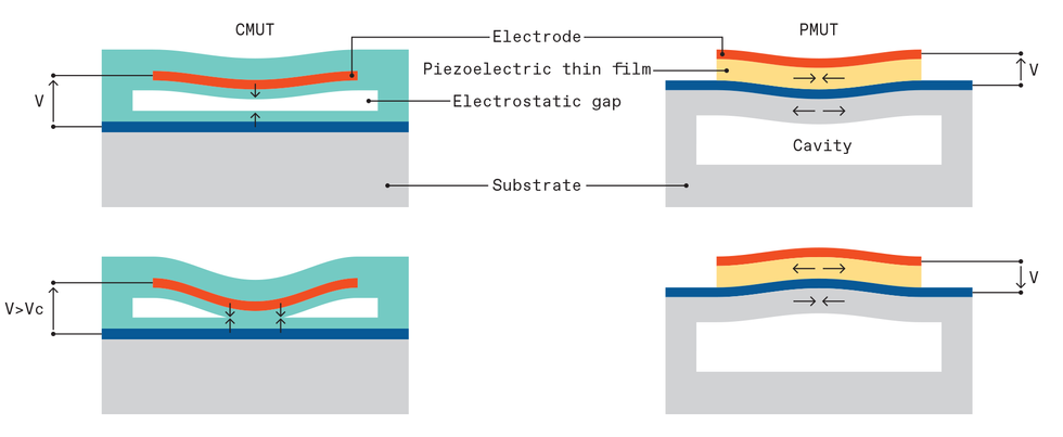
Two MEMS ultrasound architectures have emerged. In the
capacitive micromachined ultrasonic transducer (CMUT) design, attractive forces pull and flex the membrane toward the substrate. When an oscillating voltage is added, the membrane vibrates like a struck drumhead. Increasing the voltage causes the electrostatic forces to overcome the restoring forces of the membrane, causing the membrane to collapse onto the substrate. In the piezoelectric micromachined ultrasonic transducer (PMUT) architecture, voltages applied to the piezoelectric material cause it to expand and contract in thickness and from side to side. Because the lateral dimension is much larger, the piezo disk diameter changes significantly, bending the whole structure.
To provide 3D information, these handheld probes take multiple 2D slices of the anatomy and then use machine learning and AI to construct the necessary 3D data. Built-in AI-based algorithms can also help doctors and nurses precisely place needles in desired locations, such as in challenging vasculature or in other tissue for biopsies.
The AI developed for these probes is so good that it may be possible for professionals untrained in ultrasound, such as nurse midwives, to use the portable probes to determine the gestational age of a fetus, with accuracy similar to that of a trained sonographer, according to
a 2022 study in NEJM Evidence. The AI-based features could also make the handheld probes useful in emergency medicine, in low-income settings, and for training medical students.
Just the beginning for MEMS ultrasound
This is only the beginning for miniaturized ultrasound. Several of the world’s largest semiconductor foundries, including TSMC and ST Microelectronics, now do MEMS ultrasound chip production on 300 and 200 mm wafers, respectively.
In fact, ST Microelectronics recently formed a dedicated “Lab-in-Fab” in Singapore for thin-film piezoelectric MEMS, to accelerate the transition from proofs of concept to volume production.
Philips Engineering Solutions offers CMUT fabrication for CMUT-on-CMOS integration, and Vermon in Tours, France, offers commercial CMUT design and fabrication. That means startups and academic groups now have access to the base technologies that will make a new level of innovation possible at a much lower cost than 10 years ago.
With all this activity, industry analysts expect ultrasound MEMS chips to be integrated into many different medical devices for imaging and sensing. For instance, Butterfly Network, in collaboration with
Forest Neurotech, is developing MEMS ultrasound for brain-computer interfacing and neuromodulation. Other applications include long-term, low-power wearable devices, such as heart, lung, and brain monitors, and muscle-activity monitors used in rehabilitation.
In the next five years, expect to see miniature passive medical implants with ultrasound MEMS chips, in which power and data are remotely transferred using ultrasound waves. Eventually, these handheld ultrasound probes or wearable arrays could be used not only to image the anatomy but also to read out vital signs like internal pressure changes due to tumor growth or deep-tissue oxygenation after surgery. And ultrasound fingerprint-like sensors could one day be used to measure blood flow and heart rate.
One day, wearable or implantable versions may enable the generation of passive ultrasound images while we sleep, eat, and go about our lives.
-
Laser-Driven Pacemaker Guides Ailing Hearts With Light

When 11 University of Chicago researchers reported that they had installed and tested their laser-driven pacemaker in a live animal, their Nature paper laid claim only to “the first minimally invasive optical stimulation of an in vivo pig heart.”
They appear to have achieved more than that.
Together, the team designed, fabricated, and tested what may be the first photovoltaic semiconductor pacemaker. Their approach to the technology could also transform treatments that require stimulating nerves, muscles, or hearts. En route, the Chicago group evaluated photovoltaic materials and developed devices for experiments with cultured heart cells, rodent hearts, in vivo mice and rats, and finally, a sedated adult pig. The device they ultimately developed, for implantation in a pig, was a flexible, two-centimeter square photovoltaic membrane, which was implanted via minimally invasive surgery.
Graduate student Pengju Li says he pulled the multidisciplinary research team together from two Chicago labs—Bozhi Tian’s biology-and-electronics materials group and Narutoshi Hibino’s translational cardiovascular research group.
In the culminating experiment, the Chicago surgical team reported in their Nature paper that they inserted the 4-cm2 membrane through a 1-cm slit in the skin between the animal’s ribs. The membrane is thin: the semiconductor layer is just 4 micrometers thick, stabilized on a 21 µm polymer matrix. All but the very finest human hair is thicker. The membrane is also lightweight—around 0.05 grams. Conventional pacemakers, even the new leadless designs (they are “without wires,” not “without element 82”), are 100 to 1000 times heavier.
Consequently, the pacemaker self-adhered to the right ventricle. This natural adhesion is sufficient for short applications in acute treatment, says lab head Bozhi Tian.
Using an endoscope and optical fibers inserted through the same one-centimeter slit, the researchers lit up a selected spot on the pacemaker with a series of one-millisecond laser pulses. (In earlier experiments, they used laser beams as narrow as 10 µm to localize the stimulus.)
The pacemaker overrode the heart’s normal rhythm and accelerated it from 71 to about 120 beats per minute. By moving the beam from one target to another, they also reported they achieved multisite activation—stimulating muscles in both the right and left heart ventricles to produce the kind of contraction patterns that might be needed to return an arrhythmic heart to a normal beat in cardiac resynchronization therapy (CRT).
Tian says the team’s first clinical target will be temporary CRT for patients at risk for sudden cardiac death. CRT in these cases requires brief implantations of a few days to a few months. “CRT definitely requires precise multisite pacing, and we are aiming to apply it to this clinical application first,” Tian says.
Leadless and Minimally Invasive
Conventional pacemakers’ leads are often threaded through a major vein and into one of the heart’s chambers, where the electrode contacts the heart wall. The pacemaker electronics and battery are tucked into a pocket under the skin of the upper chest and attached to the ends of the leads outside the heart.
Leads can, however, sometimes obstruct the veins, interfere with heart valves, or irritate tissues inside the heart—sometimes with serious or even fatal results.
Leadless pacemakers, on the drawing boards since the 1970s, reached the market and clinic in 2014. These are small, self-contained packages, combining very-long-life batteries and pacing electronics. The tiny cylinders weigh just a few grams and are 3 to 4 cm long—somewhere between an AAA battery and a large vitamin capsule in size and shape. Like conventional pacemakers, they are inserted into the heart, threaded through a major vein into a ventricle.
The Chicago design, on the other hand, adheres to the outside of the heart, what’s called the epicardial surface. Nothing is inserted into the heart’s chambers, and nothing is stuck into the external heart muscle. The prototype the Chicago team develop did, they say, require the 1-cm incision in the skin and a 2-cm window in the pericardium (the sac surrounding the heart) for setting the pacemaker and admitting the fiber optic bundle to deliver laser light. And in the prototype, the laser is externally powered. These are challenges to address, the team says, during development.
Li and Tian also say they developed their minimally invasive implantation approach to reduce stress on the subject and promote recovery. “Perhaps, the most fulfilling aspect for me is the initial design of the minimally invasive surgery tool,” Tian says. He says he was inspired by watching an orthopedic surgeon insert polymer implants to repair a torn rotator cuff.
The Heart of the Pacemaker
To build their pacemaker, the Chicago team would need material with a specific set of properties. It would have to produce enough current to stimulate the heart, and the current would have to be highly localized in time and space. To find their best candidate, Li, Tian and their colleagues say they turned to solar cells, testing out a range of alternatives including non-crystalline silicon and single-crystal silicon. The semiconductor they used—a nanoporous single-crystal silicon type—yielded tightly constrained currents in both time and space, the researchers say.
Since then, Tian says, “Pengju has significantly expanded this system to include porous/nanoporous silicon heterojunctions created by other synthetic methods.”
By now, Tian says, “The fabrication process is super-easy. Specifically, the etching process that yields the nanoporous structure takes only about a minute or less in a solution. I believe this makes scalable and low-cost fabrication feasible.”
Igor Efimov, professor of biomedical engineering at Northwestern University in Chicago, wrote in a commentary accompanying the Nature paper that the development offers “exciting proof of concept shows the enormous potential that the technology holds, and suggests that photoelectric devices could eventually transform a range of therapies, including those requiring neural, muscular and cardiac stimulation.”
-
Wearable Sticker Reads Even the Smallest Finger Motions

Scientists in China have developed a thin, flexible sticker that can turn subtle hand, finger, and mouth motions into words or commands. The new wearable sensor, developed by researchers at the Guilin University of Electronic Technology and Beijing Normal University, could support assistive technologies for people who struggle with basic movements, such as those with disabilities or patients recovering from conditions such as strokes.
“We wanted to create something that could make a difference in their lives by enhancing their ability to interact with their surroundings more naturally and effectively,” says Chuanxin Teng, a professor at the Photonics Research Center at the Guilin University of Electronic Technology.
Conventional motion sensors for assistive technologies are often cumbersome, lack accuracy, or are not versatile enough to cater to individual needs. “Our goal was to develop a wearable solution that was both precise in detecting gestures and comfortable for everyday use, offering a more personalized and adaptive approach to rehabilitation and assistance,” Teng says.
“These optical sensors can detect even the slightest bend of a finger or twist of a wrist.” —Zhuo Wang, Beijing Normal University
The researchers developed sensors using 2- by 4-centimeter patches of soft, flexible silicone rubber, a material that can be worn for a long time without irritating the skin. “Unlike some earlier sensors that might have been bulky or uncomfortable, our sensors are designed with wearability in mind,” says Kun Xiao, a lecturer at Beijing Normal University.
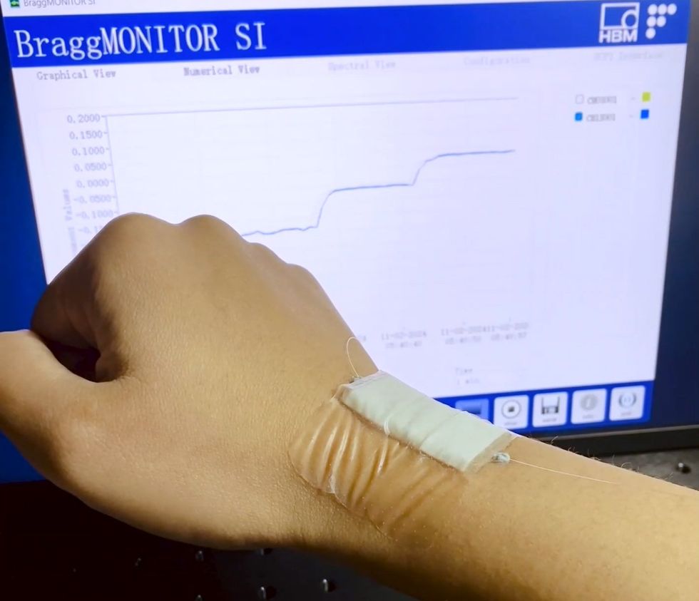 The researchers found that their flexible sensors could detect even nuanced wrist movements.Kun Xiao/Beijing Normal University
The scientists embedded fiber optics that contained etches called fiber Bragg gratings into the silicone rubber patches, which were between 1 and 3 millimeters thick. These gratings reflect specific wavelengths of light while transmitting others.
The new sensors could detect slight changes in the wavelengths of light that flow through the devices when the optical fibers are stretched or bent. “These optical sensors can detect even the slightest bend of a finger or twist of a wrist,” says Zhuo Wang, a postdoctoral researcher at Beijing Normal University. “These sensors allow for more accurate and sensitive recognition of even subtle gestures and movements.”
In one experiment with sensors attached to index fingers, a volunteer was able to send messages using Morse code, with a bent finger representing a dash and a straight finger a dot. In another experiment where a sensor was taped onto a volunteer’s cheek, the volunteer was able to silently articulate “a” and “u” sounds.
“By translating subtle movements into digital commands or communication signals, our technology could make everyday technologies more accessible,” Xiao says. “Imagine being able to communicate through gestures alone, making technology more inclusive for those with mobility or speech limitations.”
For individuals recovering from strokes or dealing with disabilities, Xiao says the sensors provide a new way to monitor rehabilitation progress. The sensors can provide detailed feedback on even subtle movements to help track improvements over time, which could potentially speed up the recovery process. Xiao adds that the sensors can also be calibrated to make them tailored to individual users’ needs.
Beyond detecting gestures and facial expressions, Xiao notes these sensors could also monitor vital signs, such as respiratory or heart rates. Xiao says that athletes, for example, could use these sensors to monitor and improve their technique in real time. Gaming systems could also provide more immersive and interactive experiences by using the sensors to incorporate natural gestures and movements into gameplay.
“Our technology could make everyday technologies more accessible.” —Kun Xiao, Beijing Normal University
The researchers now plan to make the sensor smaller and more integrated into circuitry. They also want to make the sensor more capable of withstanding moisture, heat, stretching, and daily wear and tear, all of which would make it more feasible to embed the sensor in everyday wearable items such as wristbands, gloves, or patches, Wang says. In addition, they would like to enhance the sensors’ ability to wirelessly communicate with smartphones, computers, and other medical devices to help users, caregivers, and medical professionals monitor their data in real time, he adds.
All in all, “we envision a future where wearable sensors like ours become commonplace, seamlessly integrated into clothing, accessories, or even directly onto the skin,” Xiao says. “This could lead to a world where interaction with digital devices and environments is more natural and fluid, fundamentally changing how we live, work, and play.”
The scientists detailed their findings 27 February in the journal Biomedical Optics Express.
-
Injectable Microchip Tracks Animal Health

This article is part of our exclusive IEEE Journal Watch series in partnership with IEEE Xplore.
Around the world, many pets and working animals are microchipped. It’s a simple process: A tiny transponder with an identification number is enclosed in a rice-grain-sized cylinder and injected under the skin, so that if an animal is lost it can be identified.
But electronic chips can do a lot more than hold an ID number. What if we could track a lost animal’s location? Monitor a dog’s heart rate after a medical procedure? Track the breathing rates of cattle and their calves on a livestock farm?
Injectable activity- and health-tracking sensors are indeed doable—and they could unlock novel insights and safety measures for veterinarians, farmers, animal researchers and owners of working animals and pets, according to a new study published in IEEE Sensors Journal on 22 February.
A team from North Carolina State University used off-the-shelf materials to create what they say is “the most advanced multimodal and minimally invasive injectable sensor system for animals to wirelessly monitor several of their physiological indicators and activity patterns.”
In the study, the implant provided real-time measurement of heart rate, breathing rate, movement, and temperature, along with capabilities to track blood pressure and oxygen saturation in future work.
“Animal scientists in particular tell us: We want one of these yesterday“ —Alper Bozkurt, NC State University
“Researchers use implantables already out there to track animals in studies, but they’re cumbersome: You need to put the animal under anesthesia and perform a surgery to implant this larger device,” says Alper Bozkurt, codirector of the National Science Foundation’s Center for Advanced Self-Powered Systems of Integrated Sensors and Technologies (ASSIST Center) and NC State’s Institute of Connected Sensor Systems (IConS). “We asked, why not use a much simpler and cheaper process like the microchip implant that’s done at just about every veterinary clinic?”
Bozkurt compares the injectable to a smartwatch that humans wear to track activity and basic vital statistics. “There’s a lot of little electronics behind that glass watch face; we took much of it and put it inside something really small.”
Health Tracker in a 6-Gauge Needle
Bozkurt and his colleagues Parvez Ahmmed and James Reynolds created the device in part using a commercially available system-on-a-chip. Their injectable chip system includes multiple physiological sensors, front-end circuits, a microcontroller with a wireless radio system to send measurements, Bluetooth low-energy capability, and a rechargeable battery.
The sensors leverage several different modalities: An electrocardiography sensor measures heart rate; an inertial measurement unit tracks movement and breathing rate; thermometry shows temperature. (The researchers plan to demonstrate blood-pressure and oxygen-saturation tracking in future work through a multiwavelength photoplethysmography sensor that is already part of the system.)
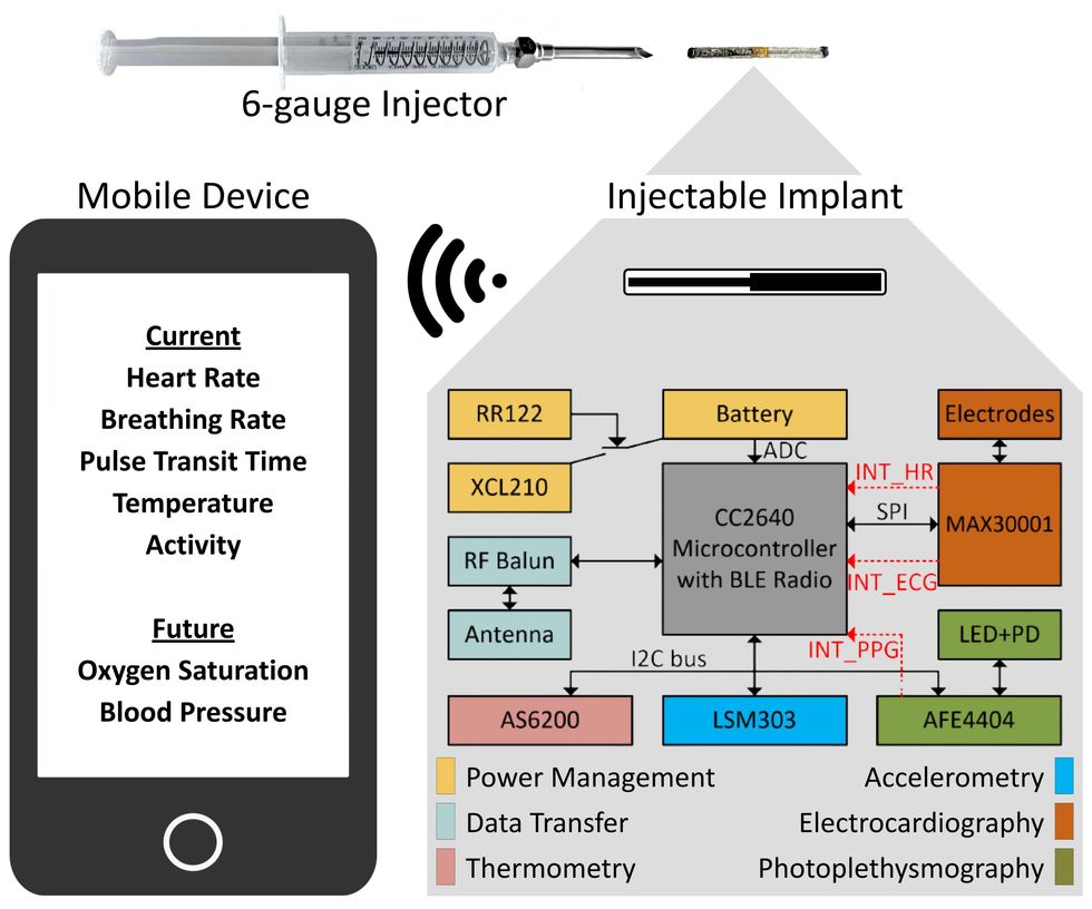 The custom implantable tracker is injected with a 6-gauge needle and tracks vital signs like heart rate, breathing rate, and temperature in addition to activity.NC State University
The researchers encapsulated the chip system in biomedical epoxy and a biocompatible synthetic polymer for insulation, then added electrically conductive epoxy at the tip to act as electrodes. This fit into 6-gauge surgical needles, which they used to inject the chip systems into both anesthetized rats and freely moving rats.
The microchip can send data from the sensors to a remote receiver within 3 meters, and the battery can last two to three months between recharges. Heart-rate and breathing-rate measurements were within close range of existing gold standards.
The team designed the system with both a biomedical epoxy and a synthetic polymer layer, so the device could be extracted and reused. “Say we use it with an animal, and a month or two later we can dissolve the outer polymer layer, recharge the battery, and encapsulate it again to produce another implant,” Ahmmed says.
Biometrics in a Smaller Package
Looking ahead, the team concluded they’ll need to build their own specialized application specific integrated circuits (ASICs) to shrink the injectable system down from 6-gauge-needle size (about 4 millimeters) to the 12- or 15-gauge (1.4–2.2 mm) needles currently used in traditional microchipping. (They have also experimented with 3D-printing electrodes using novel ceramic-based printing processes.)
“You always want to design something that’s very analogous to what already exists: the same skills, procedures, and look as a regular microchip,” Reynolds says. “But that size is a very tiny diameter so it’s been quite the technical challenge.”
Despite the challenges, the team did manage to create a smaller, battery-free version of the system that is detailed in a 4 March paper in IEEE Transactions on Biomedical Circuits and Systems.
Reynolds, who comes from a long line of farmers, noted that the injectable has several agricultural applications: a sharp increase in heart rate could alert a farmer to a livestock animal experiencing pain from, say, a fractured bone, while other vital signs could help stop a disease among herd animals before it spreads. Veterinary researchers could also use the device to monitor endangered species, on whom they cannot perform surgery to implant a large tracker, he notes.
Working animals and pets can also benefit, says Jane Russenberger, cofounder of the International Working Dog Registry, an online registry where working-dog owners can add, edit, and view electronically stored records.
Data from the injectable “could be analyzed to help with predicting the dog’s likelihood of success in a particular type of work or placement with a particular type of handler,” Russenberger says. Examples, she adds, include pets being assessed for adoption, animals offered to sale for government agencies for use in detection work, and testing the impact of training classes, socialization, and other enrichment activities for pets.
With potential applications from pet ownership, to veterinary research and practice, to farming, to working animals, Bozkurt wants to translate this system to the market and says industry interest is high.
“I can’t share the names, but I can say we have a number of companies interested,” Bozkurt says. “There are so many applications with various end users, and animal scientists in particular tell us: We want one of these yesterday.”
-
Tiny Laser Opens Door to Chip-Size Sensors

A new ultra-energy-efficient tiny laser on a chip could enable powerful medical sensors to fit within a phone, new research finds.
The new device is a kind of frequency comb—a specialized laser that generates multiple wavelengths of light, each at a regular frequency interval. On a spectrogram it would look a bit like the teeth of a comb. In the roughly quarter century since they were first developed, these “rulers for light” have revolutionized many kinds of high-precision measurement, from timekeeping to molecular detection. In addition, each line of a comb can be isolated and have properties such as its amplitude modulated to carry data over fiber optics.
However, frequency combs typically require bulky, costly, and power-hungry equipment. This has largely limited their use to laboratory settings.
Now, scientists at Stanford University employed two different methods that previous work explored to create microchip-scale frequency combs. One strategy, called optical parametric oscillation, involves bouncing beams of laser light within a crystal, resulting in light organizing itself into pulses of coherent, stable waves. The other approach, known as phase modulation, sends laser light into a cavity and then applies radio-frequency signals to control the phase of the light, generating frequency repetitions for use in combs. However, both of these strategies come with drawbacks, such as energy inefficiency and a limited ability to adjust optical parameters.
The resulting “microcomb” is just 1 by 10 millimeters in size
To overcome these challenges, the scientists experimented with a material called thin-film lithium niobate, which has a number of advantages compared to silicon, the industry standard material. Two of these properties include how a broad range of light wavelengths can pass through it, and how it can allow light beams of different wavelengths to interact with each other to generate new wavelengths.
The new material accommodated both optical parametric amplification and phase modulation within a single cavity. The resulting “microcomb” is just 1 by 10 millimeters in size. Such a compact size suggests it could find use in personal devices the size of a phone or smaller, the researchers say. It could also be easily made at conventional microchip fabs, they add.
“The most surprising aspect of this comb was how well it performed, in terms of bandwidth and spectrum and efficiency,” says Amir Safavi-Naeini, an associate professor of applied physics at Stanford University.
Instead of generating pulses of light as the researchers expected, the new microcomb unexpectedly produced a continuous output. Other combs waste power in between pulses. As a result, the scientists could reduce the input power the device required by roughly an order of magnitude.
A High Efficiency, High Performance Frequency Comb
The new device’s efficiency at converting light pumped into the cavity into a comb exceeded 93 percent. It could generate 200 comb lines spaced about 5.8 gigahertz apart across more than 1 terahertz of frequencies. It proved highly tunable by simply adjusting the radio signal applied to it. All these properties make it “extremely attractive for emerging ideas on chip-scale sensors that need to detect spectrum over broad ranges,” Safavi-Naeini says.
In addition, the device yielded a flat comb, meaning the comb lines farther away in frequency from the center did not fade in intensity. This flat nature helps boost accuracy and makes the microcomb useful in a wider variety of measurement applications.
The scientists note that spacing between comb lines could reach 50 to 100 GHz and that the device could potentially work with blue to midinfrared light. This suggests that the microcomb could find use in applications such as medical diagnostics, fiber telecommunications, LIDAR, and spectroscopy.
“We recently started working on very lightweight, low-cost, low-power greenhouse gas detection applications,” Safavi-Naeini says. “Other domains like biosensing are also very interesting.”
In the future, the scientists would like to improve the device’s performance, as well as extend its bandwidth and range of operating wavelength ranges, Safavi-Naeini says.
The scientists detailed their findings online 6 March in the journal Nature.
-
Sensory Stimulation Detoxifies the Alzheimer’s Brain
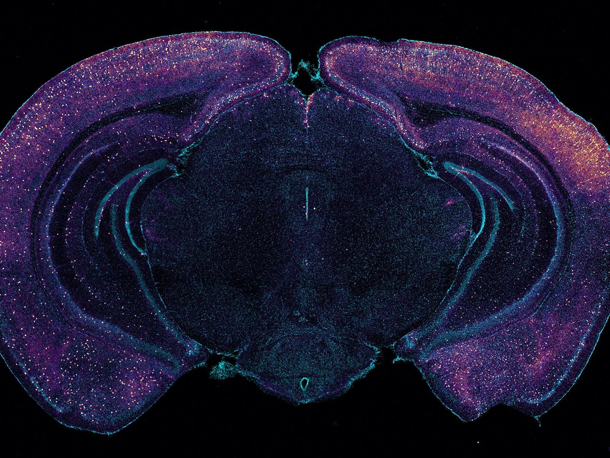
A flicker of light and a buzz of sound may hold the key to combating Alzheimer’s disease—and a new study in mice offers insights into how this unconventional therapy might work in humans.
The noninvasive brain-stimulation technology features an audiovisual disco of rhythmic 40-hertz stimuli, designed to boost brain health by enhancing neural activity at the same “gamma” frequency.
Administered for an hour each day through an integrated headset or display panel, the at-home therapy has shown promise in early clinical testing. In people with various stages of Alzheimer’s, it has been associated with preserved brain volume, strengthened connectivity between neurons, improved mental functioning, and more restful sleep, among other benefits.
A medical device startup called Cognito Therapeutics is currently evaluating the sensory therapy in a large randomized trial of people with mild-to-moderate Alzheimer’s. Meanwhile, the company’s academic cofounders—neuroscientist Li-Huei Tsai and neuroengineer Ed Boyden, both at the Massachusetts Institute of Technology (MIT)—continue to stress how the 40-Hz sync sessions induce beneficial changes in mouse models.
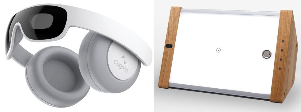 Gamma-frequency stimulation can be administered through an integrated headset [left] or with a light box [right].Left: Cognito Therapeutics; Right: OptoCeutics
In their latest paper, the MIT researchers found that this rhythmic remedy aids in the removal of beta-amyloid, the sticky protein that clumps together in the brains of those with Alzheimer’s disease. And it does so through a neural-cleansing process known as glymphatic clearance.
How does 40-Hz therapy work?
The 40-Hz therapy helps to bring more cerebrospinal fluid (CSF) into the brain. The neural juices then slosh around, accumulate beta-amyloid gunk, and flow out through specialized waste-removal channels before eventually getting eliminated through the body’s excretory pathways.
“It’s so important to understand how this works,” says Tsai, director of MIT’s Picower Institute for Learning and Memory. “It really makes the therapy that much more compelling.”
But not everyone is waiting for these kinds of mechanistic insights, let alone definitive clinical data, before jumping on the 40-Hz bandwagon.
Indeed, some companies have already begun offering consumer-oriented devices and tablet apps that deliver gamma frequency stimulation via light or sound. Marketed for “general wellness,” products such as the EVY Light—a $2,000 light box from OptoCeutics that emits a subtle, nearly imperceptible 40-Hz flicker, designed to be easier on the eyes than the intense strobe lights from other products—are geared toward people worried about potential cognitive decline. But these technologies are also not approved to treat or prevent any neurodegenerative condition.
Before making its device available for purchase, OptoCeutics did run small trials to ensure that the product was safe and produced synchronized brain rhythms in people. A randomized follow-up trial is ongoing in Denmark to see if the therapy can ameliorate various aspects of Alzheimer’s.
But trial results could take years to materialize. Full regulatory approval could take even longer. “And if we really, truly want to know how this technology is going to impact people’s lives, we have to test it out in the real world,” says OptoCeutics cofounder and CEO Mai Nguyen.
Given the minimal risk involved in using this technology, she says, the company opted to make the device available today. “The pros outweigh the cons at the moment,” Nguyen says.
The OptoCeutics platform, like every 40-Hz therapy available or in development today, traces its inspiration back to a landmark 2016 study from Tsai and her MIT team. In that work, the researchers showed how flickering white light at a 40-Hz frequency could help to synchronize neural waves in key brain areas involved in reasoning, planning, and memory.
In so doing, the therapy reduced the buildup of beta-amyloid plaques and tau tangles—hallmark features of Alzheimer’s—in the brains of mice engineered to mimic the condition.
What could 40-Hz therapy do?
This and subsequent studies from the MIT group found that both visual and auditory stimuli at 40 Hz could promote a healthier state in mouse neurons, reversing some aspects of degeneration. Additionally, this sensory experience helped to lessen inflammation caused by microglia, the brain’s immune cells.
And now, reporting in Nature, the researchers have implicated the brain’s glymphatic system in mediating the treatment’s beta-amyloid-lowering effects. What’s more, they pinpointed a key peptide-signaling molecule that neurons use to regulate CSF movement and drive glymphatic clearance.
An independent study, also published today in Nature, by neuroimmunologist Jonathan Kipnis and his colleagues at Washington University further detail how rhythmic neuronal activity of the kind induced by the 40-Hz therapy is critical to fluid perfusion and self-cleaning in the brain.
“The results are very convincing,” says Andrey Vyshedskiy, a neuroscientist at Boston University and one of the creators of AlzLife, an app that delivers gamma-frequency stimulation alongside cognitive-training exercises. Together, Vyshedskiy says, the “animal studies create a scientific foundation and a better understanding of what is changing in the brain.”
If clinical trials confirm the ability of 40-Hz stimuli to clear plaques, maintain brain structure, and slow down dementia, the therapy could emerge as an affordable and user-friendly approach to managing Alzheimer’s—especially when compared to the alternative, monoclonal antibody treatments. These amyloid-targeting drugs are not only expensive, costing tens of thousands of dollars each year, but they also pose risks of causing swelling and bleeding in the brain.
“This may be a preferred option for Alzheimer’s treatment,” says Cognito’s chief medical officer Ralph Kern. Results from the company’s pivotal trial are expected some time next year.
Cognito’s device, known as Spectris, pairs opaque glasses with built-in, flashing LEDs, plus a set of headphones. A possible drawback of this design is the necessity for users to remain stationary during treatment sessions, devoid of any external entertainment or distractions. Some might find this difficult. However, feasibility tests have shown it to be a manageable challenge, with more than 85 percent of participants consistently using the device daily throughout a six-month study.
“Maybe it’s counterintuitive,” Kern says, “but there’s something very attractive about sitting calmly for an hour and having a treatment at home. And we find that people generally are comfortable doing that.”
In addition to its Alzheimer’s study, Cognito plans to begin testing its device on people living with Parkinson’s disease and multiple sclerosis. And Annabelle Singer, a Georgia Tech neurobiologist who serves on the company’s scientific advisory board, expects the therapy to prove beneficial against other conditions, too.
Consider treatment-resistant epilepsy. In a small group of patients being evaluated for potential brain surgery, Singer and her colleagues found that 40-Hz sensory therapy could reduce the incidence of abnormal brainwave events that are indicative of a heightened propensity for seizures.
Autism, schizophrenia, stroke—any number of other brain disorders could potentially be remedied by leveraging gamma frequencies to promote synchronized neuronal activity.
“It certainly is having a beneficial activity on pathological activity that is known to affect cognition,” Singer says. “That’s indicative that this could be useful in a variety of contexts where that matters.”
-
The Quest for a DNA Data Drive

How much thought do you give to where you keep your bits? Every day we produce more data, including emails, texts, photos, and social media posts. Though much of this content is forgettable, every day we implicitly decide not to get rid of that data. We keep it somewhere, be it in on a phone, on a computer’s hard drive, or in the cloud, where it is eventually archived, in most cases on magnetic tape. Consider further the many varied devices and sensors now streaming data onto the Web, and the cars, airplanes, and other vehicles that store trip data for later use. All those billions of things on the Internet of Things produce data, and all that information also needs to be stored somewhere.
Data is piling up exponentially, and the rate of information production is increasing faster than the storage density of tape, which will only be able to keep up with the deluge of data for a few more years. The research firm Gartner
predicts that by 2030, the shortfall in enterprise storage capacity alone could amount to nearly two-thirds of demand, or about 20 million petabytes. If we continue down our current path, in coming decades we would need not only exponentially more magnetic tape, disk drives, and flash memory, but exponentially more factories to produce these storage media, and exponentially more data centers and warehouses to store them. Even if this is technically feasible, it’s economically implausible.
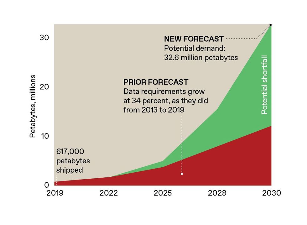 Prior projections for data storage requirements estimated a global need for about 12 million petabytes of capacity by 2030. The research firm Gartner recently issued new projections, raising that estimate by 20 million petabytes. The world is not on track to produce enough of today’s storage technologies to fill that gap.SOURCE: GARTNER
Fortunately, we have access to an information storage technology that is cheap, readily available, and stable at room temperature for millennia:
DNA, the material of genes. In a few years your hard drive may be full of such squishy stuff.
Storing information in DNA is not a complicated concept. Decades ago, humans learned to sequence and synthesize DNA—that is, to read and write it. Each position in a single strand of DNA consists of one of four nucleic acids, known as bases and represented as A, T, G, and C. In principle, each position in the DNA strand could be used to store two bits (A could represent 00, T could be 01, and so on), but in practice, information is generally stored at an effective one bit—a 0 or a 1—per base.
Moreover, DNA exceeds by many times the storage density of magnetic tape or solid-state media. It has been calculated that all the information on the Internet—which
one estimate puts at about 120 zettabytes—could be stored in a volume of DNA about the size of a sugar cube, or approximately a cubic centimeter. Achieving that density is theoretically possible, but we could get by with a much lower storage density. An effective storage density of “one Internet per 1,000 cubic meters” would still result in something considerably smaller than a single data center housing tape today.
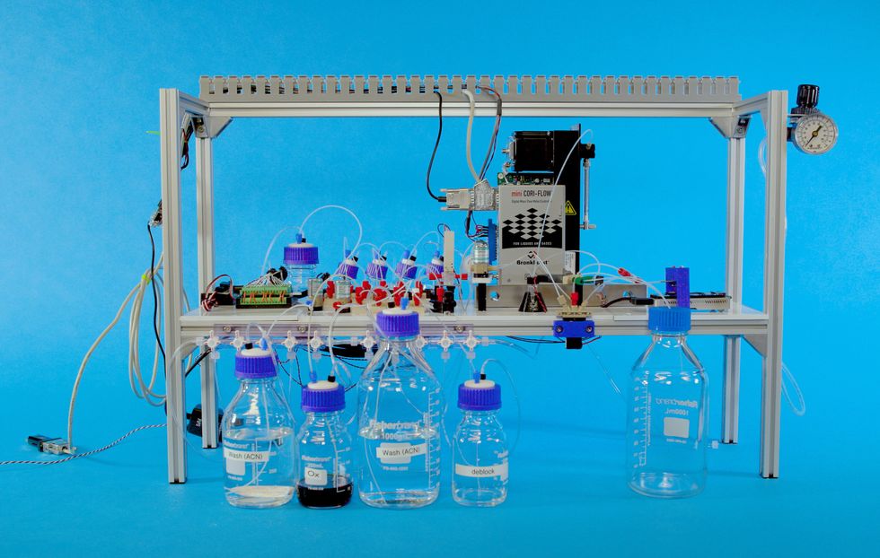 In 2018, researchers built this first prototype of a machine that could write, store, and read data with DNA.MICROSOFT RESEARCH
Most examples of DNA data storage to date rely on chemically synthesizing short stretches of DNA, up to 200 or so bases. Standard chemical synthesis methods are adequate for demonstration projects, and perhaps early commercial efforts, that store modest amounts of music, images, text, and video, up to perhaps hundreds of gigabytes. However, as the technology matures, we will need to switch from chemical synthesis to a much more elegant, scalable, and sustainable solution: a semiconductor chip that uses enzymes to write these sequences.
After the data has been written into the DNA, the molecule must be kept safe somewhere. Published examples include drying small spots of DNA on
glass or paper, encasing the DNA in sugar or silica particles, or just putting it in a test tube. Reading can be accomplished with any number of commercial sequencing technologies.
Organizations around the world are already taking the first steps toward building a DNA drive that can both write and read DNA data. I’ve participated in this effort via a collaboration between
Microsoft and the Molecular Information Systems Lab of the Paul G. Allen School of Computer Science and Engineering at the University of Washington. We’ve made considerable progress already, and we can see the way forward.
How bad is the data storage problem?
First, let’s look at the current state of storage. As mentioned, magnetic tape storage has a scaling problem. Making matters worse, tape degrades quickly compared to the time scale on which we want to store information. To last longer than a decade, tape must be carefully stored at cool temperatures and low humidity, which typically means the continuous use of energy for air conditioning. And even when stored carefully, tape needs to be replaced periodically, so we need more tape not just for all the new data but to replace the tape storing the old data.
To be sure, the storage density of magnetic tape has been
increasing for decades, a trend that will help keep our heads above the data flood for a while longer. But current practices are building fragility into the storage ecosystem. Backward compatibility is often guaranteed for only a generation or two of the hardware used to read that media, which could be just a few years, requiring the active maintenance of aging hardware or ongoing data migration. So all the data we have already stored digitally is at risk of being lost to technological obsolescence.
How DNA data storage works
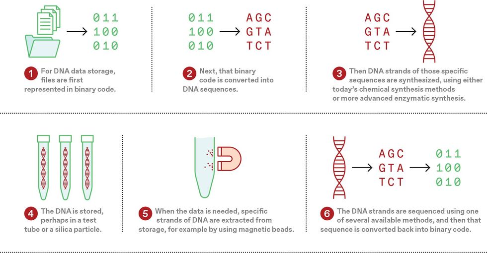
The discussion thus far has assumed that we’ll want to keep all the data we produce, and that we’ll pay to do so. We should entertain the counterhypothesis: that we will instead engage in systematic forgetting on a global scale. This voluntary amnesia might be accomplished by not collecting as much data about the world or by not saving all the data we collect, perhaps only keeping derivative calculations and conclusions. Or maybe not every person or organization will have the same access to storage. If it becomes a limited resource, data storage could become a strategic technology that enables a company, or a country, to capture and process all the data it desires, while competitors suffer a storage deficit. But as yet, there’s no sign that producers of data are willing to lose any of it.
If we are to avoid either accidental or intentional forgetting, we need to come up with a fundamentally different solution for storing data, one with the potential for exponential improvements far beyond those expected for tape. DNA is by far the most sophisticated, stable, and dense information-storage technology humans have ever come across or invented. Readable genomic
DNA has been recovered after having been frozen in the tundra for 2 million years. DNA is an intrinsic part of life on this planet. As best we can tell, nucleic acid–based genetic information storage has persisted on Earth for at least 3 billion years, giving it an unassailable advantage as a backward- and forward-compatible data storage medium.
What are the advantages of DNA data storage?
To date, humans have learned to sequence and synthesize short pieces of single-stranded DNA (ssDNA). However, in naturally occurring genomes, DNA is usually in the form of long, double-stranded DNA (dsDNA). This dsDNA is composed of two complementary sequences bound into a structure that resembles a twisting ladder, where sugar backbones form the side rails, and the paired bases—A with T, and G with C—form the steps of the ladder. Due to this structure, dsDNA is generally more robust than ssDNA.
Reading and writing DNA are both noisy molecular processes. To enable resiliency in the presence of this noise, digital information is encoded using an algorithm that introduces redundancy and distributes information across many bases. Current algorithms encode information at a physical density of 1 bit per 60 atoms (a pair of bases and the sugar backbones to which they’re attached).
 Edmon de Haro
Synthesizing and sequencing DNA has become critical to the global economy, to human health, and to understanding how organisms and ecosystems are changing around us. And we’re likely to only get better at it over time. Indeed, both the cost and the per-instrument throughput of writing and reading DNA have been improving exponentially for decades, roughly keeping up with
Moore’s Law.
In biology labs around the world, it’s now common practice to order chemically synthesized ssDNA from a commercial provider; these molecules are delivered in lengths of up to several hundred bases. It is also common to sequence DNA molecules that are up to thousands of bases in length. In other words, we already convert digital information to and from DNA, but generally using only sequences that make sense in terms of biology.
For DNA data storage, though, we will have to write arbitrary sequences that are much longer, probably thousands to tens of thousands of bases. We’ll do that by adapting the naturally occurring biological process and fusing it with semiconductor technology to create high-density input and output devices.
There is global interest in creating a DNA drive. The members of the
DNA Data Storage Alliance, founded in 2020, come from universities, companies of all sizes, and government labs from around the world. Funding agencies in the United States, Europe, and Asia are investing in the technology stack required to field commercially relevant devices. Potential customers as diverse as film studios, the U.S. National Archives, and Boeing have expressed interest in long-term data storage in DNA.
Archival storage might be the first market to emerge, given that it involves writing once with only infrequent reading, and yet also demands stability over many decades, if not centuries. Storing information in DNA for that time span is easily achievable. The challenging part is learning how to get the information into, and back out of, the molecule in an economically viable way.
What are the R&D challenges of DNA data storage?
The first soup-to-nuts automated prototype capable of writing, storing, and reading DNA was built by my Microsoft and University of Washington colleagues in 2018.
The prototype integrated standard plumbing and chemistry to write the DNA, with a sequencer from the company Oxford Nanopore Technologies to read the DNA. This single-channel device, which occupied a tabletop, had a throughput of 5 bytes over approximately 21 hours, with all but 40 minutes of that time consumed in writing “HELLO” into the DNA. It was a start.
For a DNA drive to compete with today’s archival tape drives, it must be able to write about 2 gigabits per second, which at demonstrated DNA data storage densities is about 2 billion bases per second. To put that in context, I estimate that the total global market for synthetic DNA today is no more than about 10 terabases per year, which is the equivalent of about 300,000 bases per second over a year. The entire DNA synthesis industry would need to grow by approximately 4 orders of magnitude just to compete with a single tape drive. Keeping up with the total global demand for storage would require another 8 orders of magnitude of improvement by 2030.
Exponential growth in silicon-based technology is how we wound up producing so much data. Similar exponential growth will be fundamental in the transition to DNA storage.
But humans have done this kind of scaling up before. Exponential growth in silicon-based technology is how we wound up producing so much data. Similar exponential growth will be fundamental in the transition to DNA storage.
My work with colleagues at the University of Washington and Microsoft has yielded many promising results. This
collaboration has made progress on error-tolerant encoding of DNA, writing information into DNA sequences, stably storing that DNA, and recovering the information by reading the DNA. The team has also explored the economic, environmental, and architectural advantages of DNA data storage compared to alternatives.
One of our goals was to build a semiconductor chip to enable high-density, high-throughput DNA synthesis.
That chip, which we completed in 2021, demonstrated that it is possible to digitally control electrochemical processes in millions of 650-nanometer-diameter wells. While the chip itself was a technological step forward, the chemical synthesis we used on that chip had a few drawbacks, despite being the industry standard. The main problem is that it employs a volatile, corrosive, and toxic organic solvent (acetonitrile), which no engineer wants anywhere near the electronics of a working data center.
Moreover, based on a sustainability analysis of a theoretical DNA data center performed my colleagues at Microsoft, I conclude that the volume of acetonitrile required for just one large data center, never mind many large data centers, would become logistically and economically prohibitive. To be sure, each data center could be equipped with a recycling facility to reuse the solvent, but that would be costly.
Fortunately, there is a different emerging technology for constructing DNA that does not require such solvents, but instead uses a benign salt solution. Companies like
DNA Script and Molecular Assemblies are commercializing automated systems that use enzymes to synthesize DNA. These techniques are replacing traditional chemical DNA synthesis for some applications in the biotechnology industry. The current generation of systems use either simple plumbing or light to control synthesis reactions. But it’s difficult to envision how they can be scaled to achieve a high enough throughput to enable a DNA data-storage device operating at even a fraction of 2 gigabases per second.
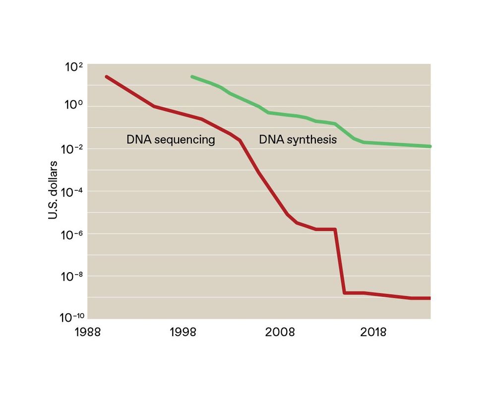 The price for sequencing DNA has plummeted from $25 per base in 1990 to less than a millionth of a cent in 2024. The cost of synthesizing long pieces of double-stranded DNA is also declining, but synthesis needs to become much cheaper for DNA data storage to really take off.SOURCE: ROB CARLSON
Still, the enzymes inside these systems are important pieces of the DNA drive puzzle. Like DNA data storage, the idea of using enzymes to write DNA is not new, but commercial enzymatic synthesis became feasible only in the last couple of years. Most such processes use an enzyme called
terminal deoxynucleotidyl transferase, or TdT. Whereas most enzymes that operate on DNA use one strand as a template to fill in the other strand, TdT can add arbitrary bases to single-stranded DNA.
Naturally occurring TdT is not a great enzyme for synthesis, because it incorporates the four bases with four different efficiencies, and it’s hard to control. Efforts over the past decade have focused on modifying the TdT and building it into a system in which the enzyme can be better controlled.
Notably, those modifications to TdT were made possible by prior decades of improvement in reading and writing DNA, and the new modified enzymes are now contributing to further improvements in writing, and thus modifying, genes and genomes. This phenomenon is the same type of feedback that drove decades of exponential improvement in the semiconductor industry, in which companies used more capable silicon chips to design the next generation of silicon chips. Because that feedback continues apace in both arenas, it won’t be long before we can combine the two technologies into one functional device: a semiconductor chip that converts digital signals into chemical states (for example, changes in pH), and an enzymatic system that responds to those chemical states by adding specific, individual bases to build a strand of synthetic DNA.
The University of Washington and Microsoft team, collaborating with the enzymatic synthesis company
Ansa Biotechnologies, recently took the first step toward this device. Using our high-density chip, we successfully demonstrated electrochemical control of single-base enzymatic additions. The project is now paused while the team evaluates possible next steps.Nevertheless, even if this effort is not resumed, someone will make the technology work. The path is relatively clear; building a commercially relevant DNA drive is simply a matter of time and money.
Looking beyond DNA data storage
Eventually, the technology for DNA storage will completely alter the economics of reading and writing all kinds of genetic information. Even if the performance bar is set far below that of a tape drive, any commercial operation based on reading and writing data into DNA will have a throughput many times that of today’s DNA synthesis industry, with a vanishingly small cost per base.
At the same time, advances in DNA synthesis for DNA storage will increase access to DNA for other uses, notably in the biotechnology industry, and will thereby expand capabilities to reprogram life. Somewhere down the road, when a DNA drive achieves a throughput of 2 gigabases per second (or 120 gigabases per minute), this box could synthesize the equivalent of about 20 complete human genomes per minute. And when humans combine our improving knowledge of how to construct a genome with access to effectively free synthetic DNA, we will enter a very different world.
The conversations we have today about biosecurity, who has access to DNA synthesis, and whether this technology can be controlled are barely scratching the surface of what is to come. We’ll be able to design microbes to produce chemicals and drugs, as well as plants that can fend off pests or sequester minerals from the environment, such as arsenic, carbon, or gold. At 2 gigabases per second, constructing biological countermeasures against novel pathogens will take a matter of minutes. But so too will constructing the genomes of novel pathogens. Indeed, this flow of information back and forth between the digital and the biological will mean that every security concern from the world of IT will also be introduced into the world of biology. We will have to be vigilant about these possibilities.
We are just beginning to learn how to build and program systems that integrate digital logic and biochemistry. The future will be built not from DNA as we find it, but from DNA as we will write it.
This article appears in the March 2024 print issue.
-
Prosthetic Arm Provides Sense of Heat and Cold

Feeling warmth or its brisk absence on the fingertips or hand can all too easily be taken for granted. Of course, most upper-limb-amputee wearers of prosthetic arms and hands cannot access those sensations. Yet, researchers at the Swiss Federal Institute of Technology (EPFL) in Écublens, Switzerland, have developed a new technology that could provide a feeling of temperature through a prosthetic hand as if it were an “intact” one.
“It not only measures but also mimics the thermal properties of the finger.” —Solaiman Shokur, Swiss Federal Institute of Technology
The system, which the engineers named MiniTouch, takes advantage of a neurological phenomenon the research team discovered last year called “phantom heat.” The phenomenon, they discovered, can make a prosthetic’s surface feel as if it were the user’s own skin, without requiring further surgery or implantation into the user. Phantom heat sensations occur when an amputee feels as though temperatures felt on their remaining limb are in fact coming from a part of the body that is no longer there. This is similar to other phantom sensations like touch, which the researchers say are experienced by roughly 80 percent of amputees.
The MiniTouch system works by connecting temperature sensors on the prosthetic hand’s fingertips to a temperature controller and a small pad of thermally conductive material. The conductive pad, located somewhere on the limb that can induce the feeling of phantom heat, is either heated or cooled to match the temperature measured at the fingertip.
Solaiman Shokur, a senior scientist of the Translational Neuroengineering group at EPFL and the principal researcher in the MiniTouch study, says that a fair portion of how materials feel actually stems from their thermal characteristics. “The reason metal feels colder than glass is because it cools your skin down from 32 °C to room temperature more quickly,” says Shokur. “We managed to reproduce that sort of signature thermal drop with our sensor. It not only measures but also mimics the thermal properties of the finger.”
Shokur says that phantom heat stems from nerves continuing to grow after an amputation, coupled with the way the brain processes sensory information and, presumably, continues to infer signals from parts of the body that are no longer there. Nerves, that is, still ping the parts of the sensory brain that handle signals like “pinky finger hot” or “thumb cold.”
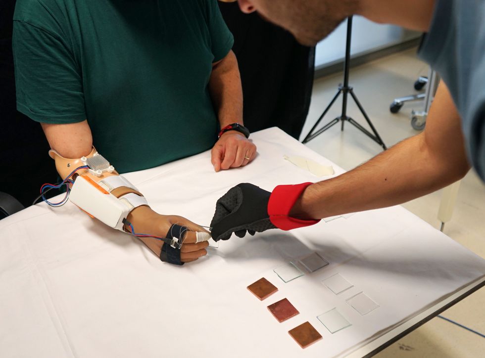 Wearers of the MiniTouch arm performed well, not only sensing heat and cold differences but also discovering via touch alone the differences between materials such as fabric or glass. TNE laboratory/EFPL
To test the device’s accuracy, the researchers had an amputee volunteer carry out a battery of experiments in which they judged the temperatures of small objects they grabbed with their prosthesis. One forearm amputee, for instance, could perfectly discriminate between cold objects, room-temperature objects, and hot objects. The same subject could also perfectly discern the difference between three materials—glass, copper, and plastic—using their MiniTouch hand.
The MiniTouch system is one of several prosthetic advances that bring back senses lost in amputation. Previous work has developed robotic hands that transmit feelings of pressure to the user, allowing them to grasp delicate objects much more carefully than with only eyesight to guide them. ‘‘The most impressive for me was when the experimenter placed the sensor on his own body,” the amputee noted above said, as quoted in the research report. “I could feel the warmth of another person with my phantom hand. It was like having a connection with someone.’’
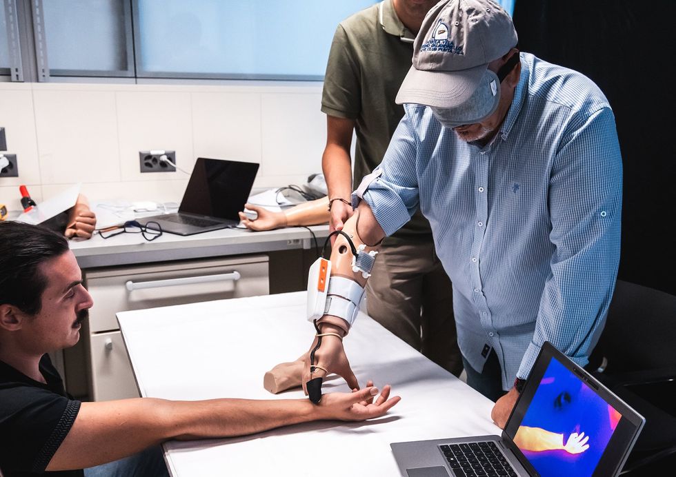 “I could feel the warmth of another person with my phantom hand,” one study participant reported. “It was like having a connection with someone.’’Caillet/EPFL
Shokur says the researchers designed the device to build into and work with any powered prosthetic, which may mean that MiniTouch could be one module in larger prosthetic systems. While the team are not currently developing the system into a stand-alone commercially available product, Shokur says they’ve patented the technology and have attracted industry interest already.
Shokur says they plan to add other senses to the device—as demonstrated in another recent paper from the group—that enable the user to feel an object’s wetness. “We’ve shown that with the exact same system we can detect levels of moisture in samples,” says Shokur. “We don’t have receptors for wetness in our skin. We rely mainly on thermal cues. Our MiniTouch system allows amputees to discriminate moisture with the same accuracy as their intact hand.”
A case report of the team’s MiniTouch research was published this week in the CellPress journal Med.